



-
Geasure Medical
-
1
-
ISO 13485 \ CE \ FDA 510(k) Cleared \ Free Sale Certificate\ MDSAP
-
Peek+Titanium Coating
-
Custom service supported
-
7–14 Days (OEM: 15–30 Days)
Artificial Cervical Disc: A Mobile-Bearing Prosthesis for C3–C7 Replacement
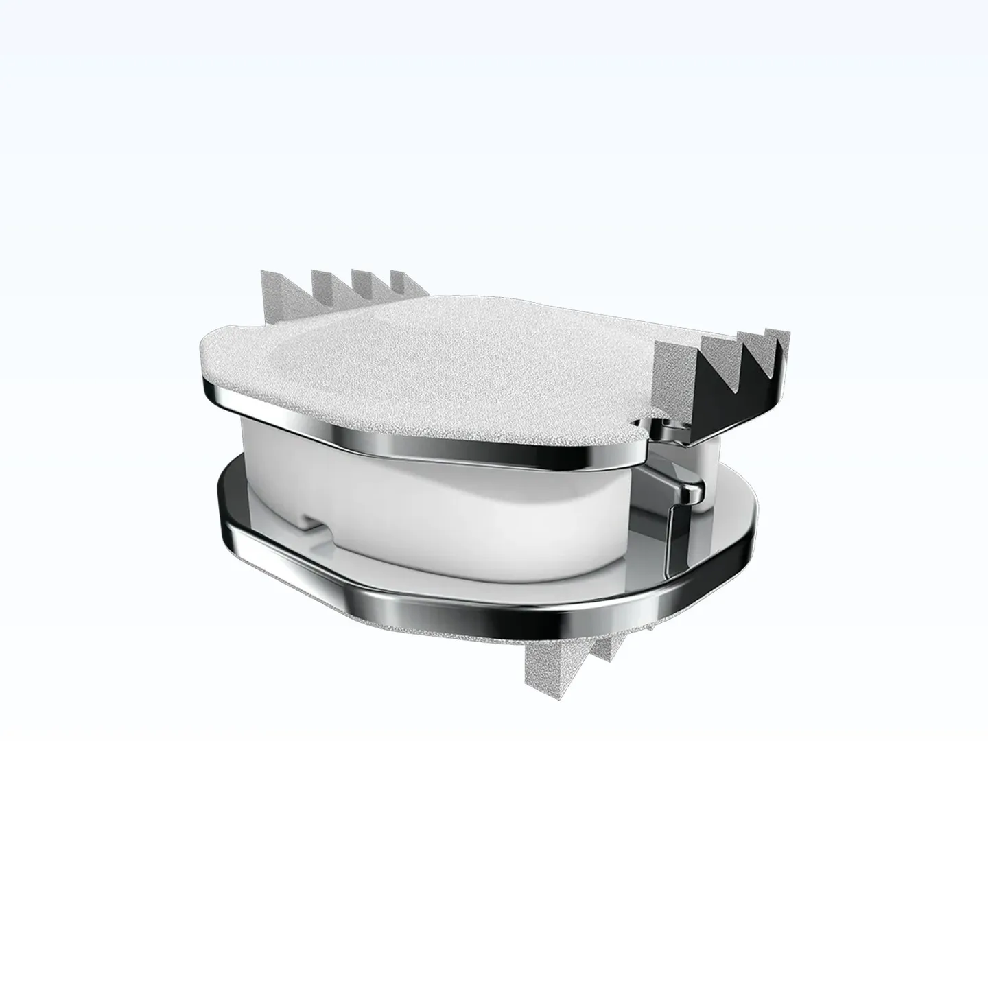
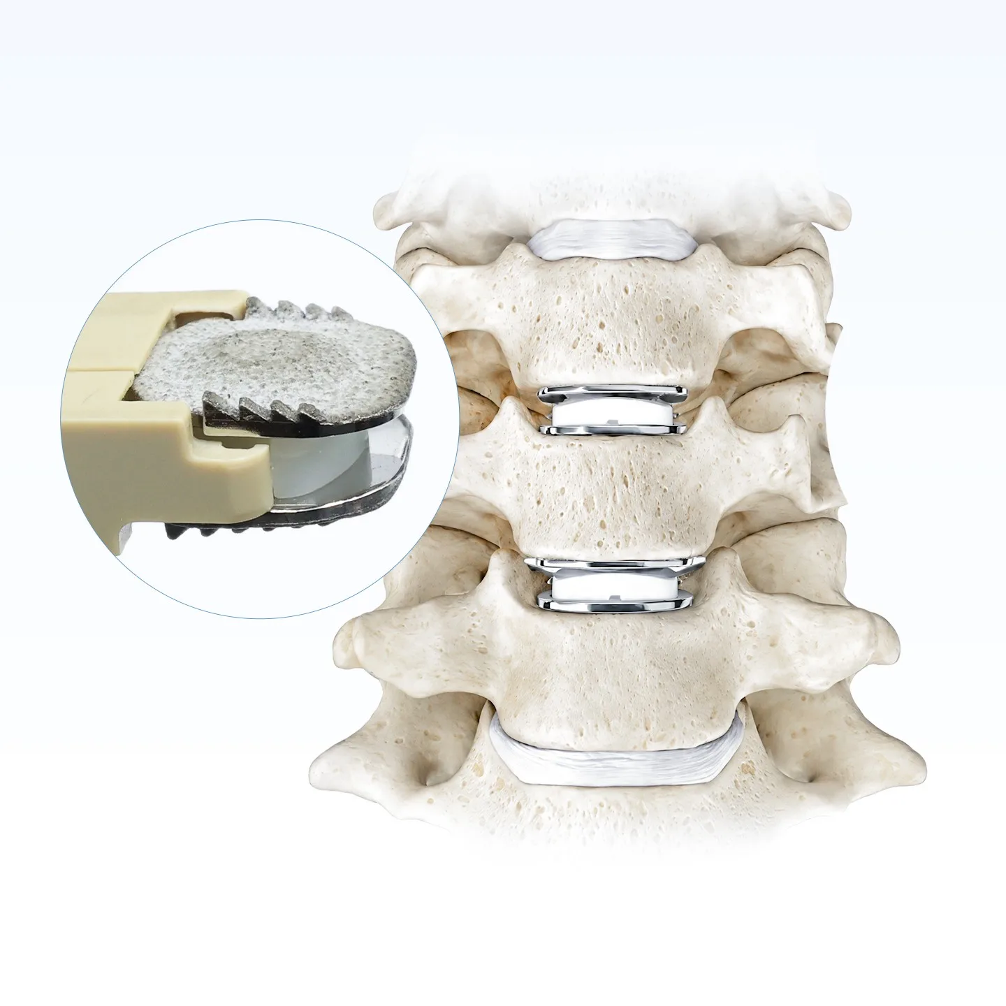
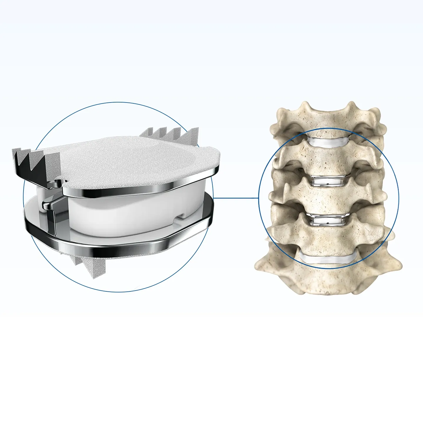
The Geasure artificial cervical disc is a mobile-bearing cervical disc prosthesis implanted after anterior cervical discectomy to restore segmental height and preserve motion at the treated level. Two cobalt-chromium-molybdenum endplates are separated by an ultra-high-molecular-weight polyethylene (UHMWPE) core that moves between them, so the articulation takes place at the core rather than at the bone–implant interface.
It is available in 16 size configurations across five footprints, with heights from 4.5 mm to 7.0 mm, and is intended for skeletally mature patients at C3–C7 involving one or two levels.
Three Materials, Three Different Jobs
Each component is chosen for one job: the endplates carry load and hold fixation, the coating drives bony ongrowth, and the core provides the bearing surface.
The endplates are machined from high-density cobalt-chromium-molybdenum alloy — a material with a long history in joint replacement, and one that stays visible on radiographs. On the bone-facing side they carry a plasma-sprayed layer of hydroxyapatite and titanium alloy powder, which gives the surface the roughness that bone can grow into.
Between them sits the UHMWPE core. It is the part that wears, so it is deliberately separated from the fixation interface: the plates hold, the core moves.
Material grades and coating thickness are stated in the technical file and confirmed on the inspection documents supplied with each batch.
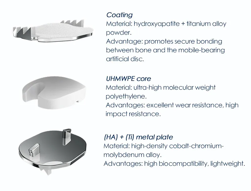
| Component | Material | Function |
|---|---|---|
| Endplate coating | Hydroxyapatite (HA) + titanium alloy powder, plasma-sprayed | Porous surface for bony ongrowth and secondary stability at the endplate–bone interface. |
| Bearing core | Ultra-high-molecular-weight polyethylene (UHMWPE) | Wear-resistant articulation with high impact resistance; carries the motion between the plates. |
| Metal endplates | High-density cobalt-chromium-molybdenum (CoCrMo) alloy | Load-bearing structure with high biocompatibility; radiopaque for radiographic follow-up. |
| Fixation teeth | Machined on the endplate rims, laterally inclined | Resist implant migration while the coating establishes biological fixation. |
How the Mobile Bearing Preserves Motion
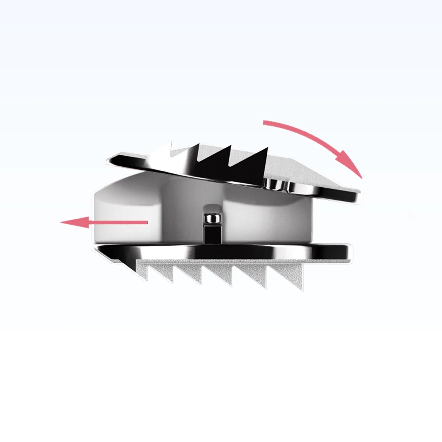
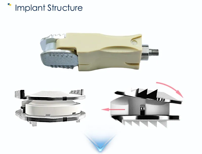
The core is not fixed to either endplate. It can translate and rotate between two polished surfaces, so the segment can flex, extend, bend laterally and rotate — and can combine those movements, the way a native disc does.
That architecture separates two things that a fixed-bearing design has to trade off: motion and fixation. The plates stay seated on the endplates while the articulation happens at the core, so the bone–implant interface is not the moving joint. Motion is carried by a replaceable wear surface rather than by the fixation interface.
- Independent and coupled motion — translation and rotation can occur together, as in the native cervical segment.
- Bearing away from bone — the sliding interface is the core, not the endplate–bone junction.
- Height restored — the core thickness sets the distraction of the segment, and is selected from the 4.5–7.0 mm range.
Three Features Aimed at the Three Common Failure Modes
Cervical disc prostheses tend to fail in one of three ways: stiffness at the segment, migration of the implant, or incomplete bony fixation. Each feature below maps to one of them.
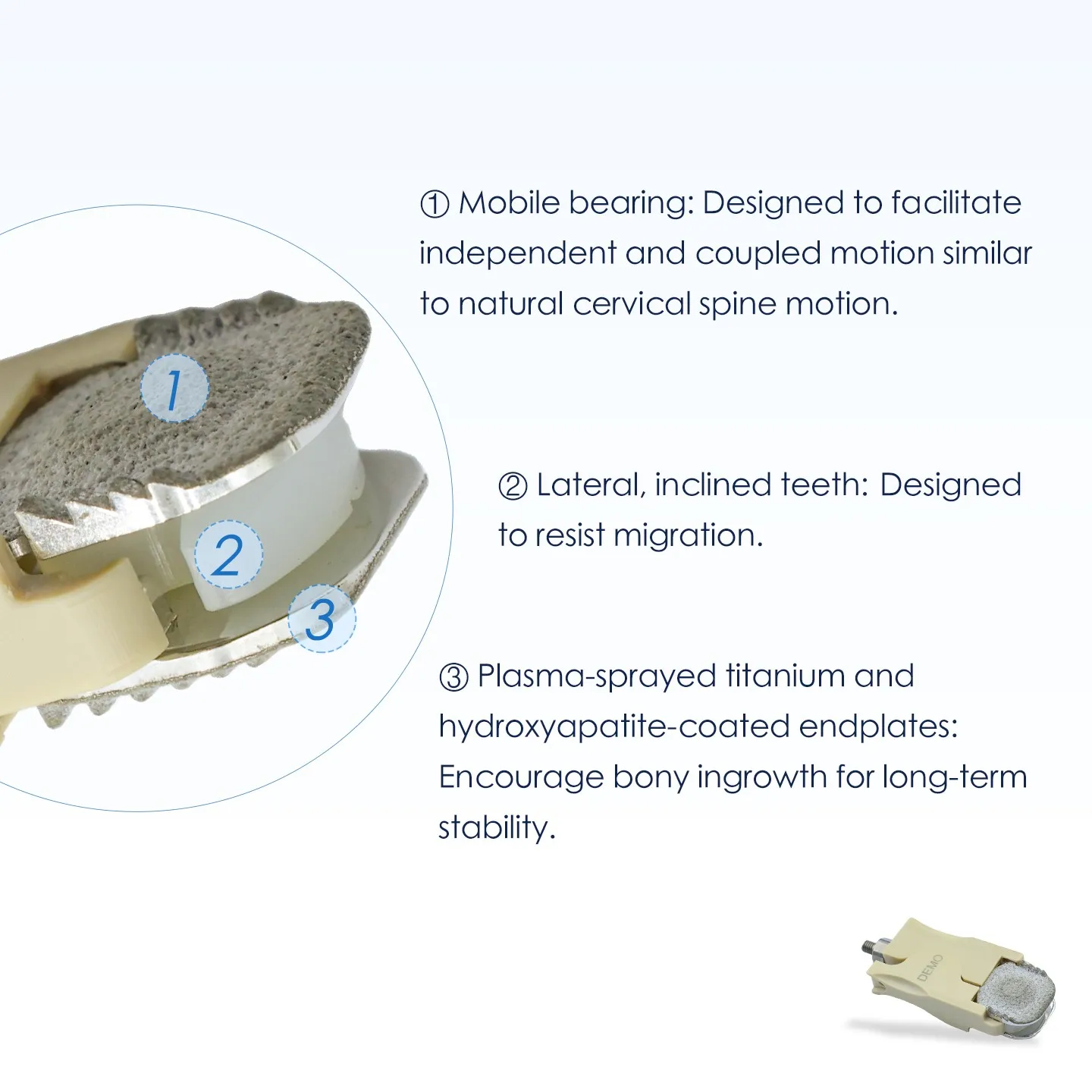
Mobile bearing
Independent and coupled motion between the plates, designed to follow natural cervical spine motion instead of forcing the segment into a fixed pivot.
Lateral, inclined teeth
Teeth machined along the endplate rims engage the vertebral body and are angled to resist migration in the early postoperative period.
Plasma-sprayed HA + Ti
A roughened hydroxyapatite and titanium coating on both endplates encourages bony ingrowth for long-term stability.
The three features work as a sequence rather than as three separate selling points: the teeth hold the implant while the coating establishes bone ongrowth, and the core keeps the segment moving throughout — so the fixation interface is never asked to act as a joint.
16 Configurations Across Five Footprints
Footprint is given as width × depth in millimetres; height is the assembled implant height. Five footprints cover small to large cervical endplates, and the heights step in 1.0 mm increments from 4.5 mm to 7.0 mm — enough resolution to match the distracted disc space rather than forcing a nearest-size fit.
Not every footprint is available in every height: 17 × 13 omits 6.0 mm, and 19 × 15 is offered in 6.0 mm only. The matrix below shows the 16 released combinations.
| Footprint (mm) | 4.5 | 5.0 | 6.0 | 7.0 |
|---|---|---|---|---|
| 15 × 13 | ||||
| 15 × 15 | ||||
| 17 × 13 | — | |||
| 17 × 15 | ||||
| 19 × 15 | — | — | — | |
| Total | 16 size configurations | |||
Footprint = width × depth. Height is the assembled implant height in millimetres. Catalogue codes are issued per configuration on the current price list.
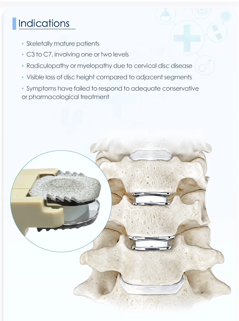
Indications: Skeletally Mature Patients, C3–C7, One or Two Levels
The implant is intended for cervical disc replacement in skeletally mature patients at levels C3 to C7, involving one or two levels, where conservative treatment has already been given an adequate trial.
- Skeletally mature patients — the endplate must accept the fixation teeth and the coated surface.
- C3 to C7, one or two levels — the current indication covers single- and two-level disease.
- Radiculopathy or myelopathy caused by cervical disc disease.
- Visible loss of disc height compared with adjacent segments.
- Failed conservative treatment — symptoms persist after adequate conservative or pharmacological management.
Demonstration Units for Handling and Seating Practice
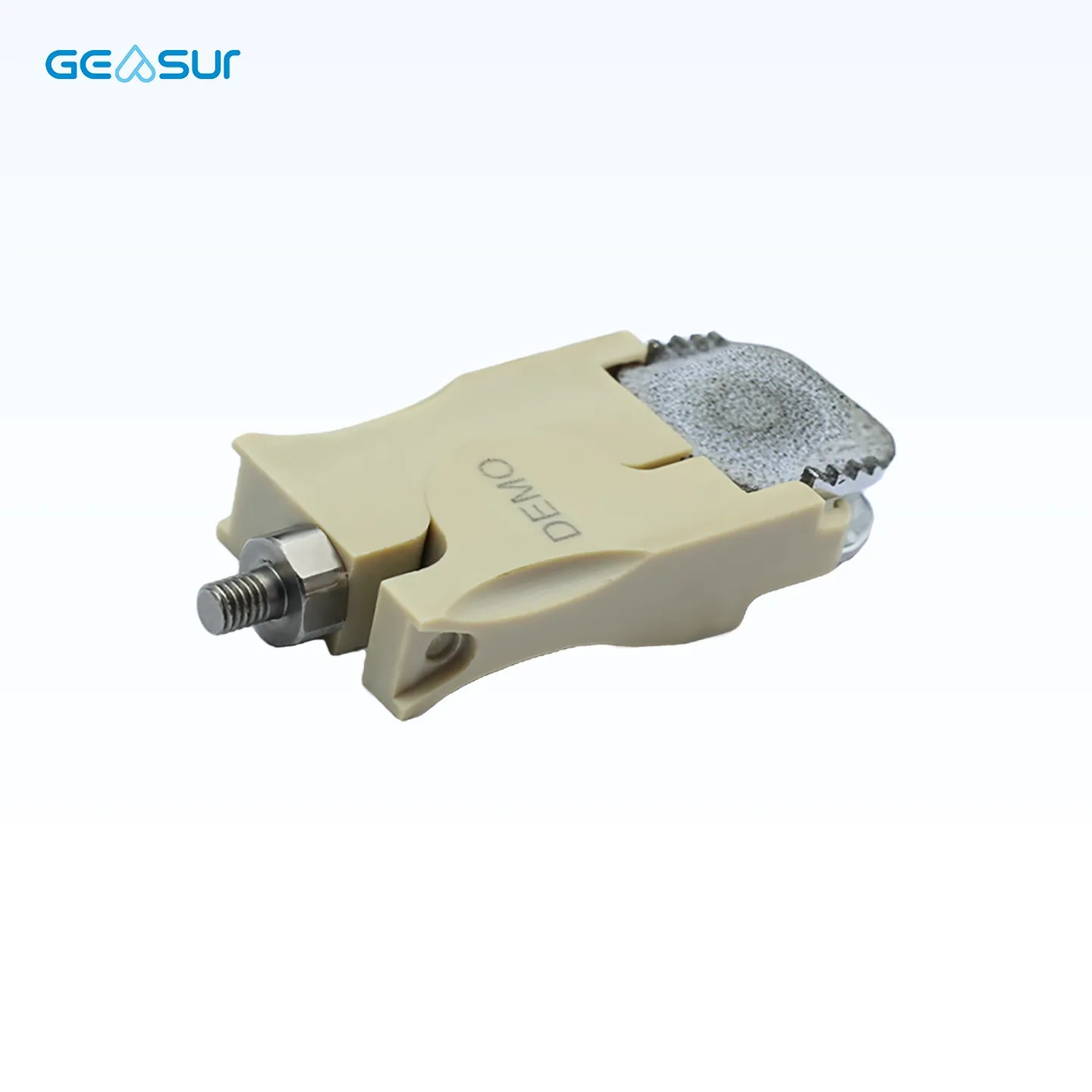
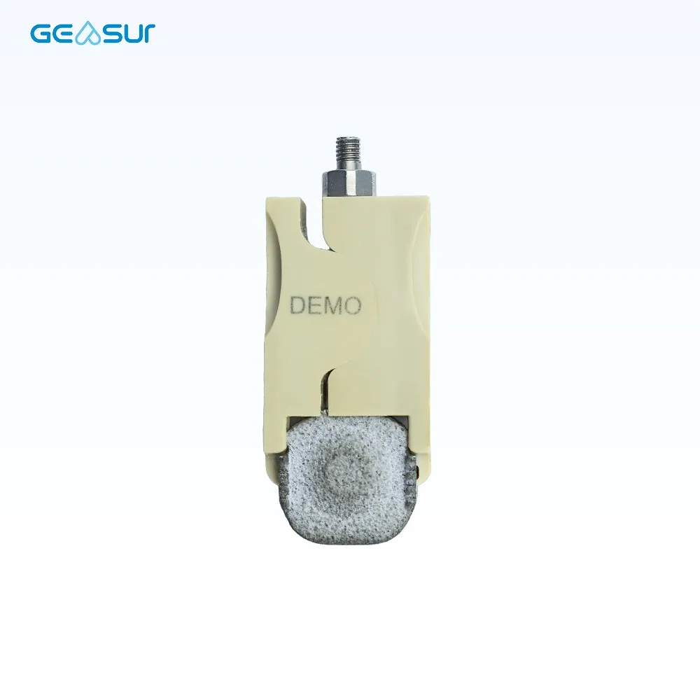
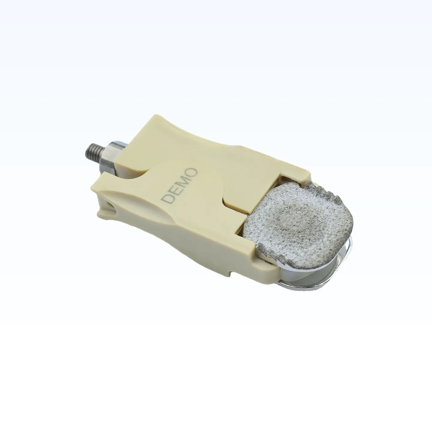
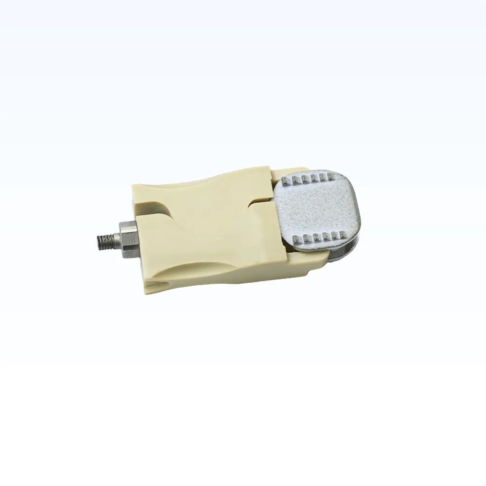
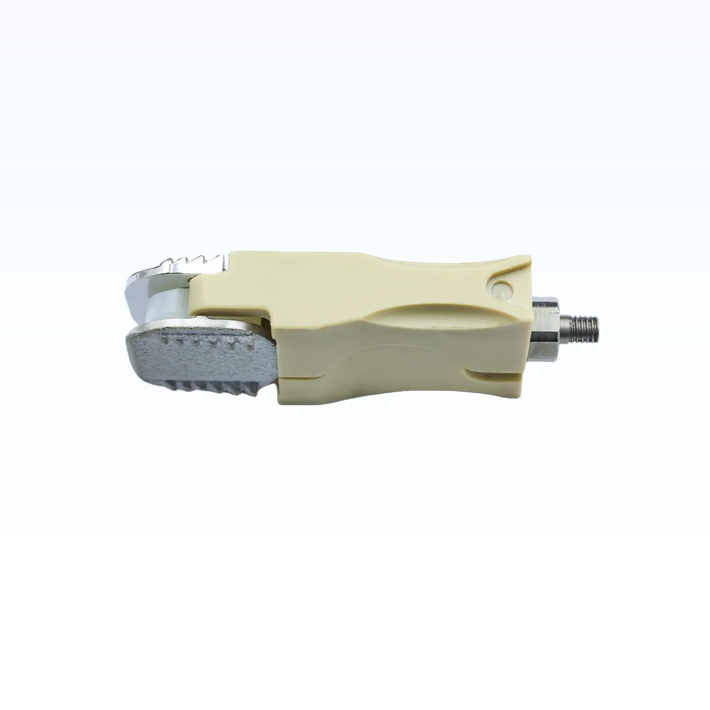
The units below carry a threaded holder and a DEMO marking. They are supplied for demonstration, training and handling practice — sizing, orientation and seating rehearsal — not for implantation.
Imaging Appearance and Multi-Level Constructs
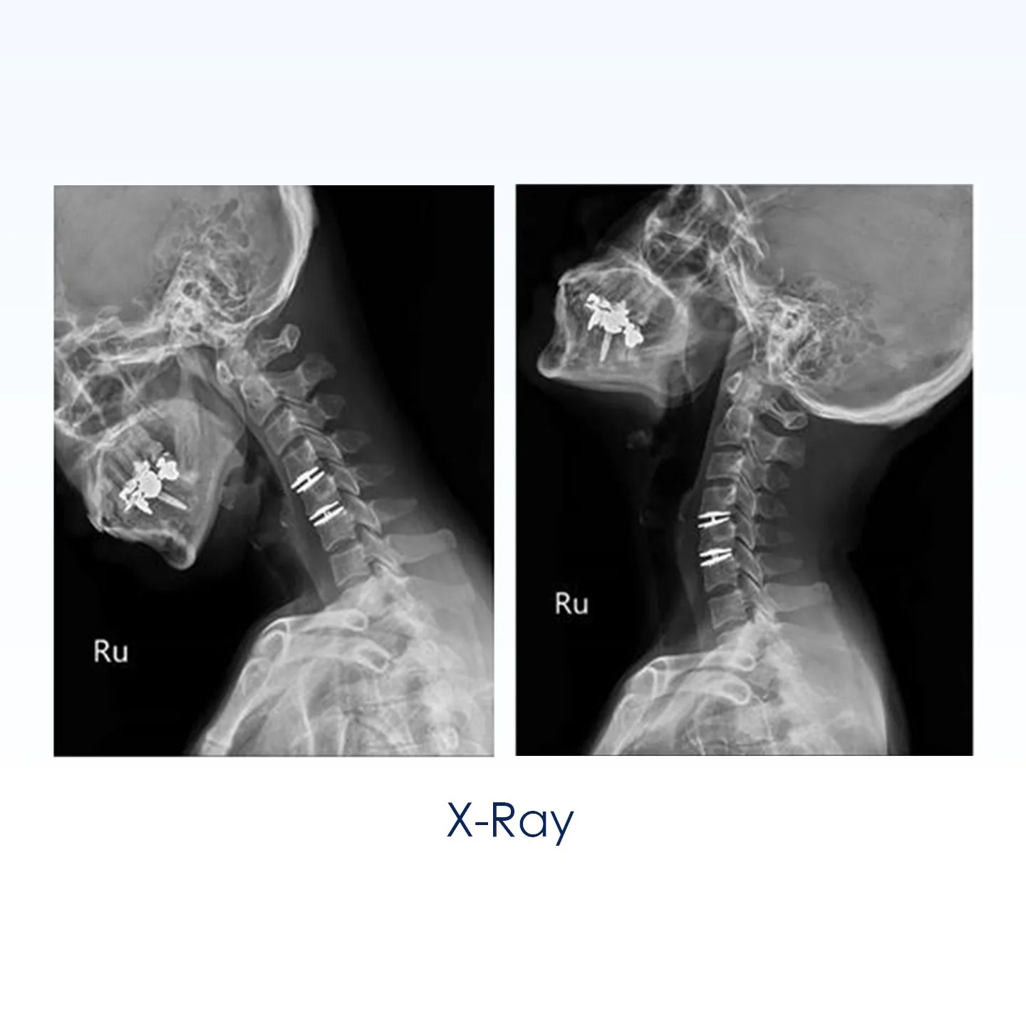
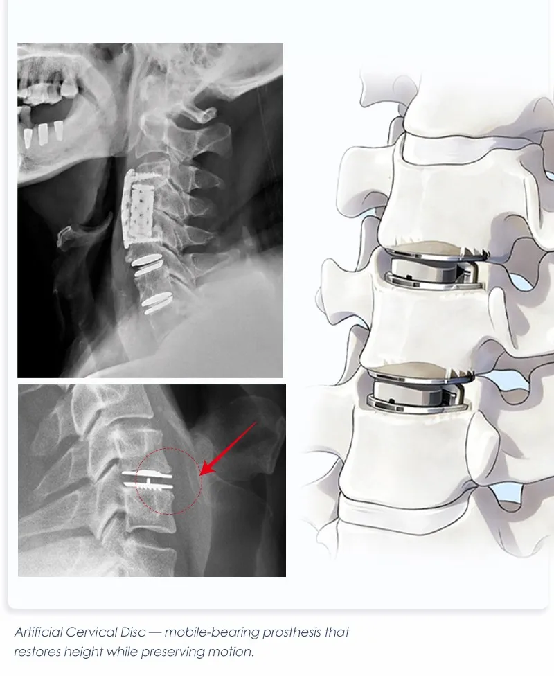
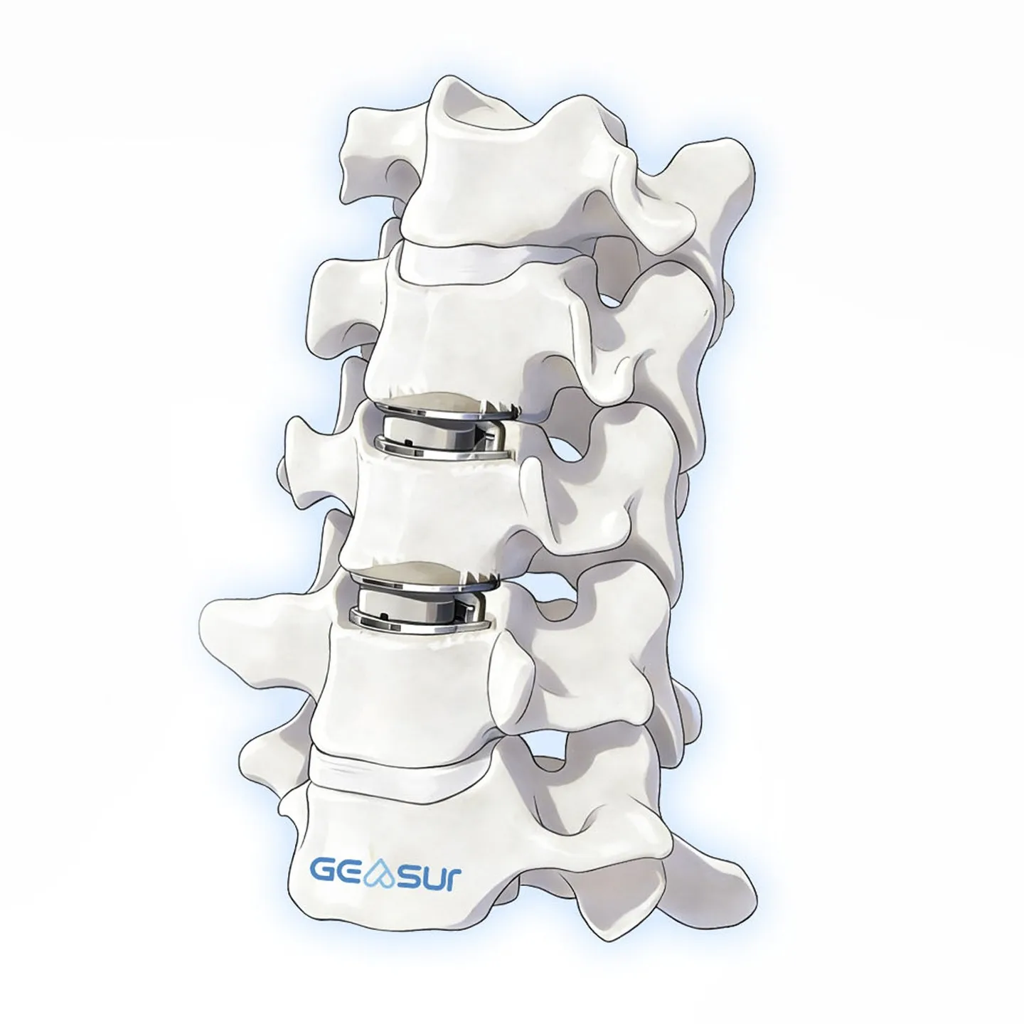
The cobalt-chromium endplates are radiopaque and the UHMWPE core is radiolucent, so a lateral radiograph shows two defined plates with a clear disc space between them — a simple way to check level, height and plate seating during and after surgery.
Surgical Sequence: From Discectomy to Verification
A cervical disc replacement follows the familiar anterior approach; what changes is endplate preparation and sizing. The sequence below is an outline for planning and training, not a substitute for the IFU.
- 1 · Approach and exposure — anterior exposure of the target level; confirm the level fluoroscopically.
- 2 · Discectomy and decompression — remove the disc and posterior osteophytes; preserve the bony endplates.
- 3 · Endplate preparation — parallel distraction, then clear the cartilaginous endplate without cutting into subchondral bone.
- 4 · Sizing — trial the footprint and height against the prepared space; the 16-configuration matrix covers 15×13 to 19×15 mm and 4.5–7.0 mm.
- 5 · Implant insertion — seat the implant on the holder, align the teeth with the anterior vertebral body, and release.
- 6 · Verification — check plate seating, height and level on lateral fluoroscopy before closure.
Frequently Asked Questions
Short answers for distributors, hospital procurement teams and surgeons evaluating the implant.
What is an artificial cervical disc?
It is a cervical disc prosthesis implanted after anterior discectomy. Instead of fusing the segment, it restores disc height with two endplates and a bearing between them, so the level can still move.
Which levels and how many can be treated?
The current indication covers skeletally mature patients at C3 to C7, involving one or two levels, with radiculopathy or myelopathy from cervical disc disease and reduced disc height.
What materials are used?
High-density cobalt-chromium-molybdenum endplates, a plasma-sprayed hydroxyapatite and titanium coating on the bone-facing surfaces, and an ultra-high-molecular-weight polyethylene core that forms the mobile bearing.
How many sizes are available?
Sixteen configurations across five footprints — 15×13, 15×15, 17×13, 17×15 and 19×15 mm — with heights of 4.5, 5.0, 6.0 and 7.0 mm, subject to the footprint.
Does the implant preserve motion?
The mobile bearing is designed to allow independent and coupled motion similar to the natural cervical segment, because the core is free to translate and rotate between the plates. Actual range of motion after surgery depends on the patient, the level and the technique.
How does it appear on imaging?
The cobalt-chromium plates are radiopaque and the polyethylene core is radiolucent, so a lateral radiograph shows two plates with a visible gap between them. MRI after implantation should follow the facility's protocol for metallic implants.
Is OEM or private-label supply available?
Yes. Size mix, packaging, labelling, laser marking and documentation can be configured for OEM/ODM projects; the instrument and trial set is quoted with the implant configuration.
Ordering, Documentation and OEM Supply
The implant is supplied in single-use packaging in 16 size configurations. Distributors can order a standard size mix or a project-specific mix built around the case profile of their market; both are quoted against the confirmed configuration, labelling and documentation scope.
- Size range: 16 configurations, five footprints, heights 4.5–7.0 mm
- Project options: size mix, packaging, labelling, laser marking, private label
- Documentation: size chart, IFU, material and inspection documents, regulatory documents as applicable to the market
Related cervical products are listed under spine implants and spine systems.
Evaluating a cervical disc replacement portfolio?
Send the target market, expected size mix and annual volume. We will return the configuration, the trial and instrument requirements, and the documentation scope.
View spine implant rangePage last reviewed: November 2026. Sizes, materials and indications follow the current Geasure technical file; specifications may change without notice. This page is product information, not medical advice.


