-
Geasure Medical
-
1
-
ISO 13485 \ CE \ FDA 510(k) Cleared \ Free Sale Certificate\ MDSAP
-
Stainless steel
-
Custom service supported
-
7–14 Days (OEM: 15–30 Days)
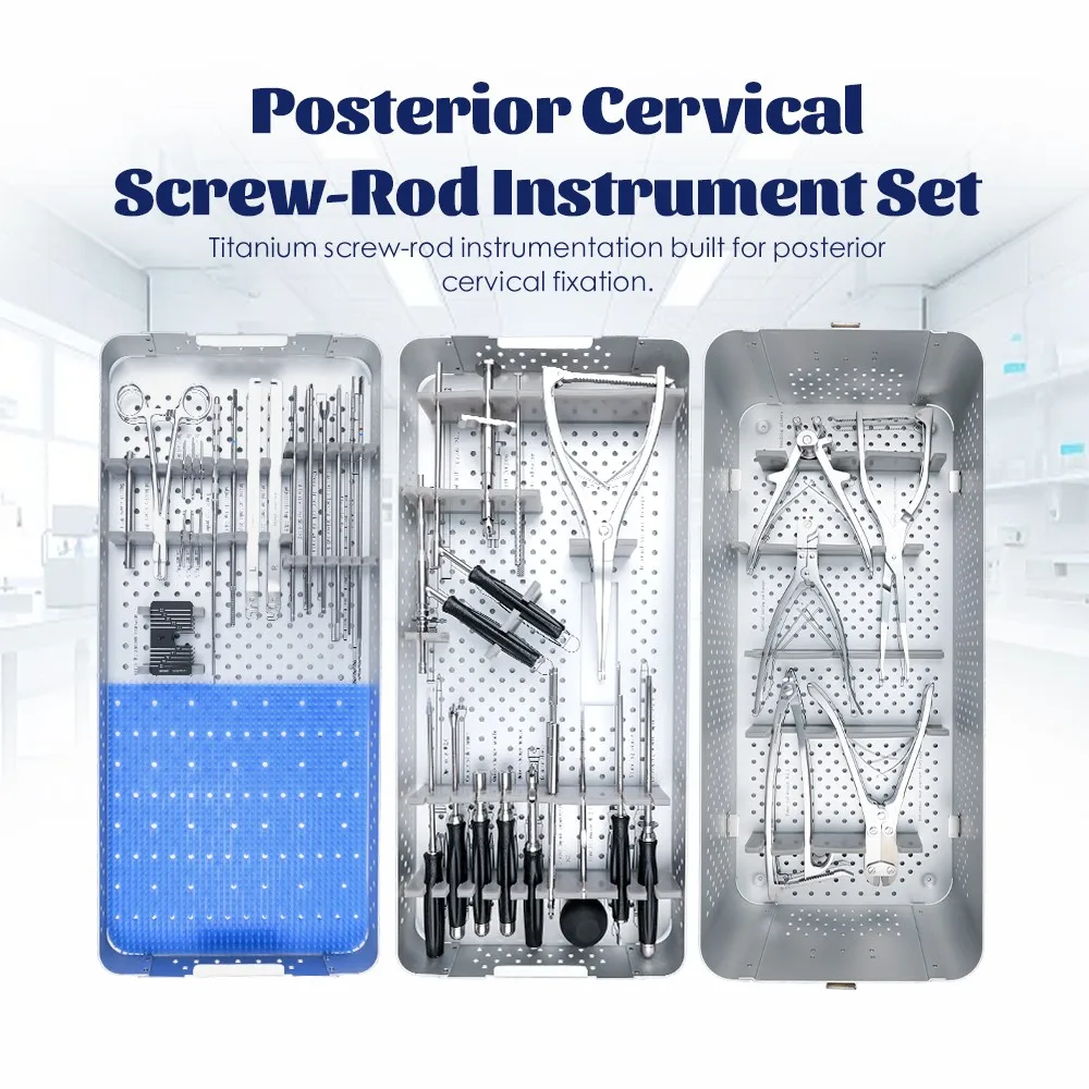
Posterior Cervical Screw-Rod Instrument Set: 37 Line Items for Cervical and Upper Thoracic Fixation
The posterior cervical screw-rod instrument set is a 37-line-item, 44-piece surgical instrument set used to prepare screw trajectories, insert polyaxial screws, contour and connect 3.5 mm rods, and apply reduction and compression during posterior cervical and upper thoracic fixation.
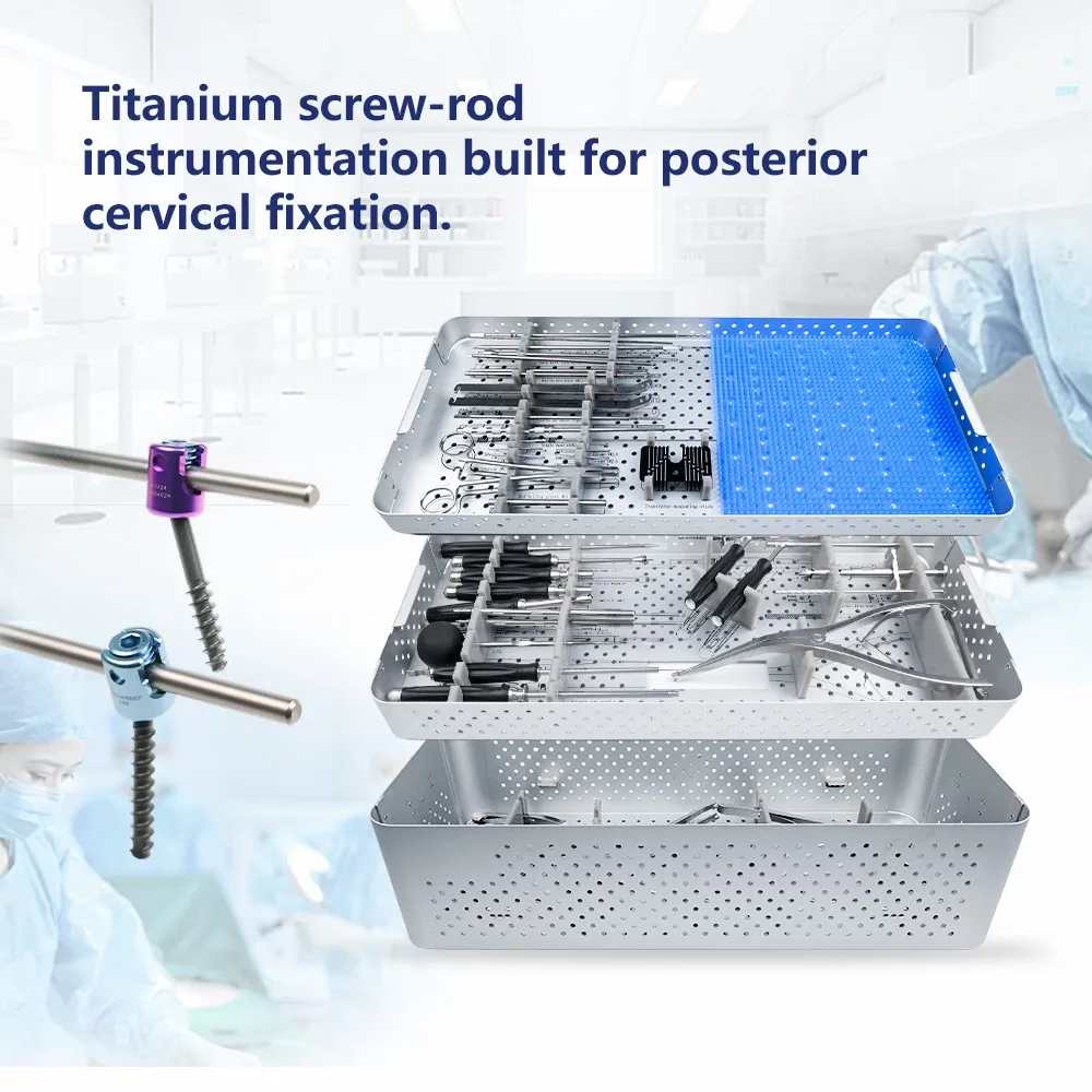
It is supplied by Geasure Medical as the matching instrument set for the posterior cervical screw-rod fixation system. The instruments cover a 3.5 mm and 4.0 mm screw range, a 3.5 mm rod platform, and a plate-clamp cross-link option, so one tray system supports the full implant portfolio instead of a single construct.
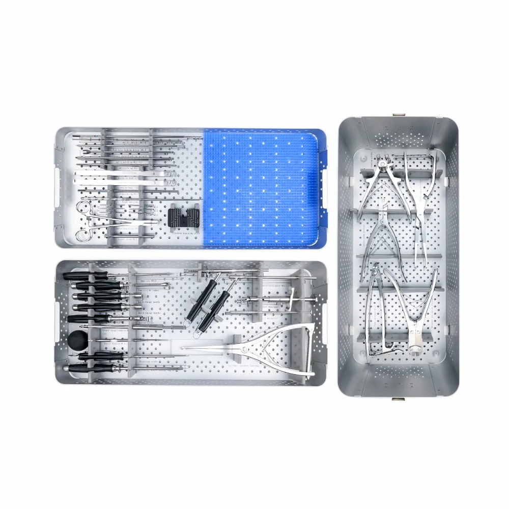
The set is organised in three perforated metal trays that stack inside one sterilization container. Each tray follows a stage of the procedure — exposure and pathway preparation, screw insertion and reduction, then rod contouring, cutting and final tightening — which shortens instrument search time in the OR and simplifies back-table counting.
Built to Match the Geasure Posterior Cervical Screw-Rod Implant System
Every diameter in this instrument set corresponds to a component in the Geasure posterior cervical screw-rod fixation system, so the tray can be planned against the implant configuration rather than adapted to it.
| No. | Implant component | Implant specification | Matching instruments in this set |
|---|---|---|---|
| 1 | Cervical polyaxial screw | Ø3.5 mm × 10–32 mm; Ø4.0 mm × 12–34 mm | Ø3.5 and Ø4.0 adjustable taps, Ø2.4 drill bit, fixed and adjustable Ø4.1 drill guides, SW2.5 universal screwdriver and set-screw drivers |
| 2 | Straight connecting rod II | Ø3.5 mm × 150 / 180 / 200 / 240 mm | Ø3.5 rod-holding forceps, Ø3.5 rod rotator, rod bender, in-situ rod benders (left / right), ratcheting and low-profile rod cutters, 240 mm rod template |
| 3 | Plate-clamp cross-link | Ø3.5 mm, 20–28 / 28–36 / 36–44 / 40–52 mm spans | Cross-link hook holder, cross-link measuring gauge, cross-link locking wrench, cross interlocking wrench |
| 4 | Set screw | M6 | SW2.5 set-screw driver, SW2.5 set-screw holding driver, counter-torque sleeve wrench, set-screw box |
The instruments are dimensioned for the implant platform, not for a generic rod system: the taps are supplied in exactly the two screw diameters of the implant range, the rod instruments are built around a 3.5 mm rod, and the cross-link group covers the full 20–52 mm span in four measured steps.
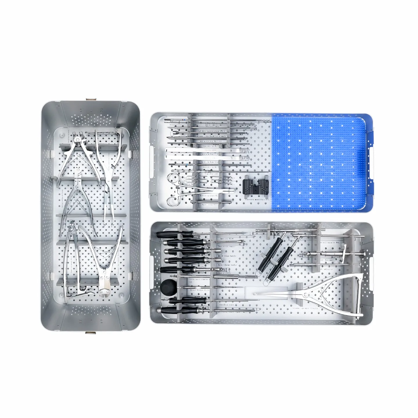
Three-Tier Tray Layout, Arranged in Surgical Order
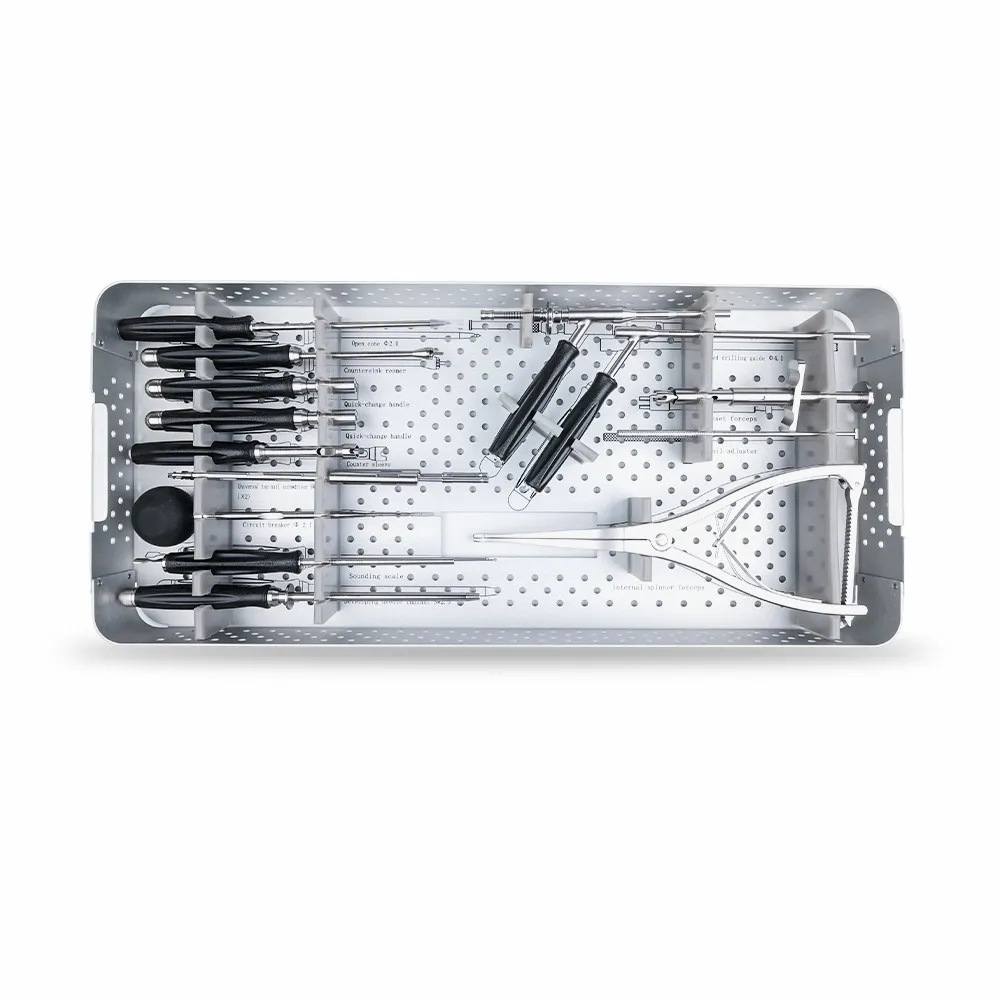
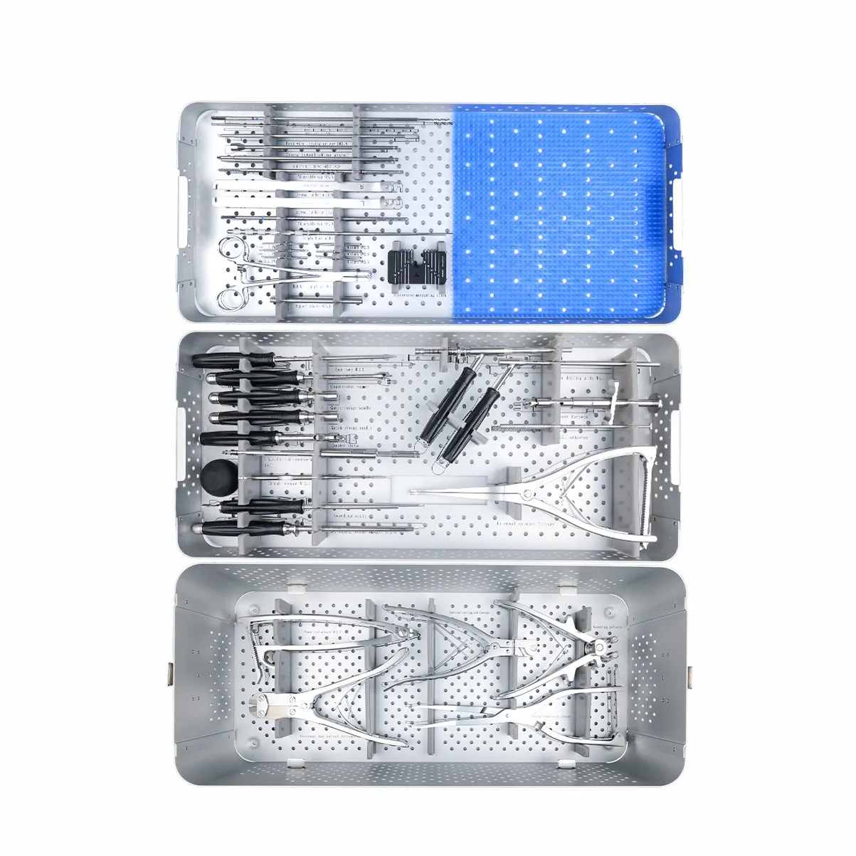
The complete set stacks in one perforated metal container with rounded corners. Perforated walls and floor allow steam penetration, so cleaning, drying, sterilization and transport happen in the same container — instruments are not repacked between the decontamination room and the OR.
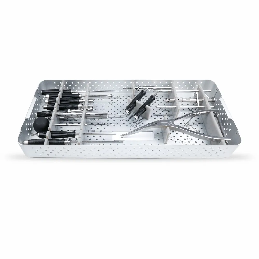
Tier 1 carries screw insertion and final tightening instruments plus a blue silicone mat for temporary screw and rod placement. Tier 2 carries pathway preparation, drilling and reduction instruments. Tier 3 carries the contouring and cutting forceps. Each instrument sits in its own silicone cradle or metal bracket, so edges and tips never contact each other in transit.
What Each Instrument Group Does
The 37 line items fall into five functional groups. Grouping them by task — rather than by tray — makes it easier to check a configuration against a surgical routine.
A · Access and pathway preparation
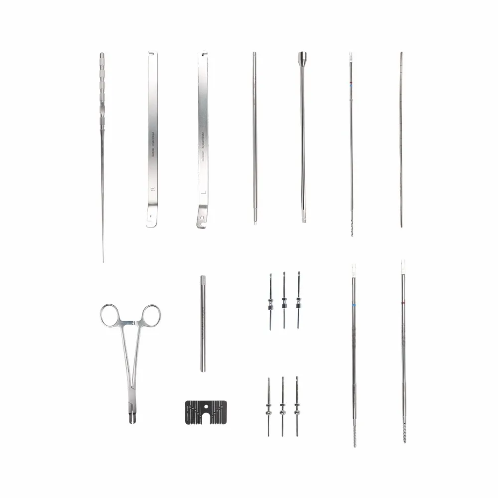
The opening group creates and verifies the screw track. A Ø2.0 open cone marks the cortical entry, a Ø2.1 probe develops the trajectory and reads the walls by hand, and the countersink reamer seats the entry so the screw head sits flush. Drilling is controlled by a Ø2.4 bit through a fixed or adjustable Ø4.1 drill guide, with a Ø5.1 support sleeve protecting soft tissue. Adjustable Ø3.5 and Ø4.0 taps cut the thread, guide pins hold the track, and the depth gauge and 240 mm rod template confirm length before selection.
B · Screw insertion and set-screw locking
Two SW2.5 universal top-loading screwdrivers drive the polyaxial screws and allow the heads to be oriented toward the rod. The SW2.5 set-screw driver, its holding version, and the counter-torque sleeve wrench complete final tightening, so torque is applied to the implant rather than to the surrounding bone. Two quick-change handles accept the taps, reamers and other shafted instruments.
C · Rod contouring and cross-link assembly
Rods are pre-bent with the rod bender or the left and right in-situ benders, rotated into the target plane with the Ø3.5 rod rotator, and guided into the screw heads with the Ø3.5 rod-holding forceps. Cross-links are sized with the transverse measuring gauge, held with the cross-link hook holder and locked with the cross-link wrenches — the same plate-clamp cross-link option offered in the implant system.
D · Reduction, compression and cutting
Reduction forceps, low-profile distractor forceps and low-profile compression forceps cover alignment and load application before final tightening. Two rod cutters — a ratcheting cutter for bench work and a low-profile cutter for in-situ trimming — finish the rod without burrs.
E · Measurement, implant handling and storage
The remaining items support sizing and logistics: the 240 mm rod template and cross-link measuring gauge confirm length, the depth gauge reads screw length, and the screw positioner adjusts an implant already in place. Screws and set screws travel in their own boxes inside the container, so implants are opened at the point of use rather than counted onto the field.
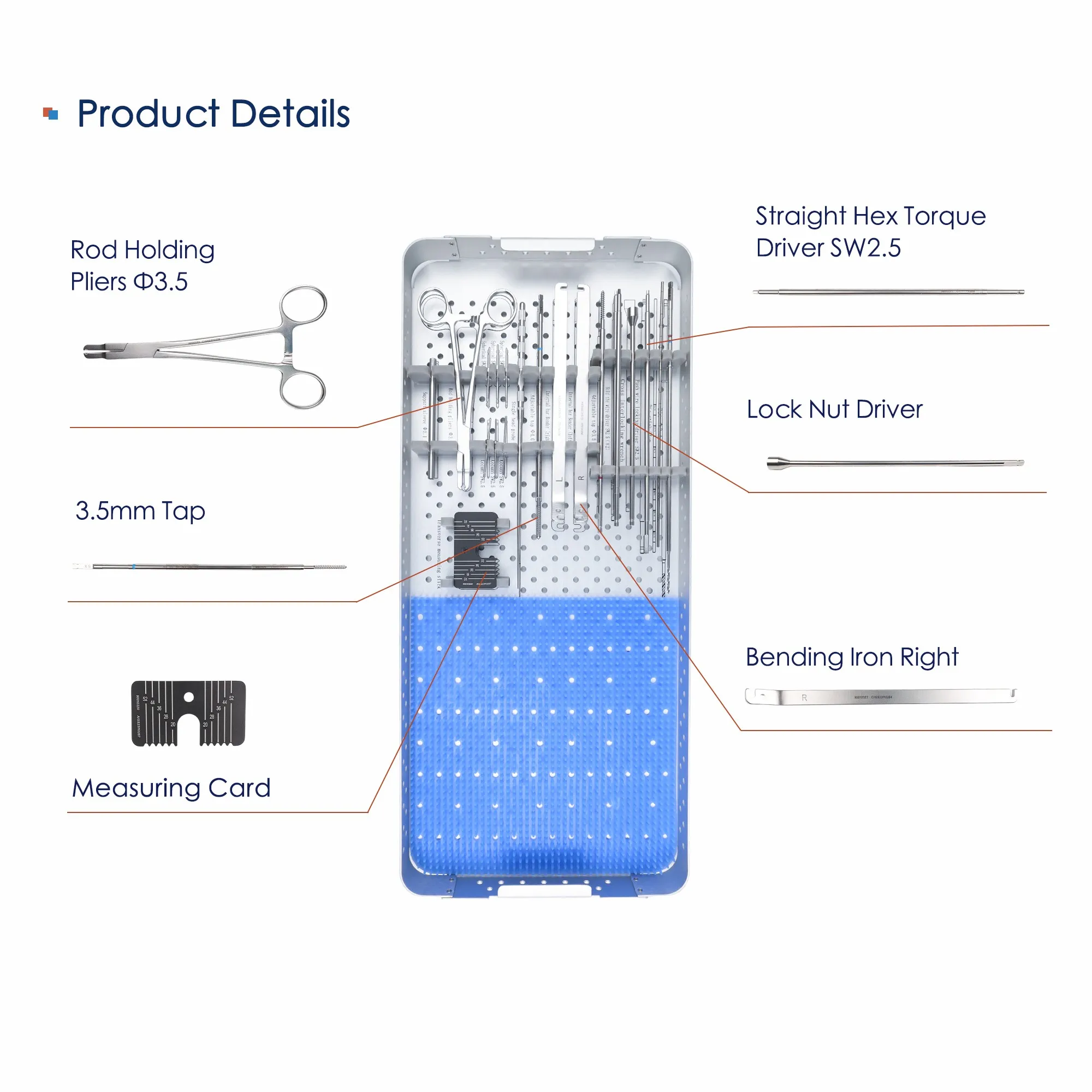
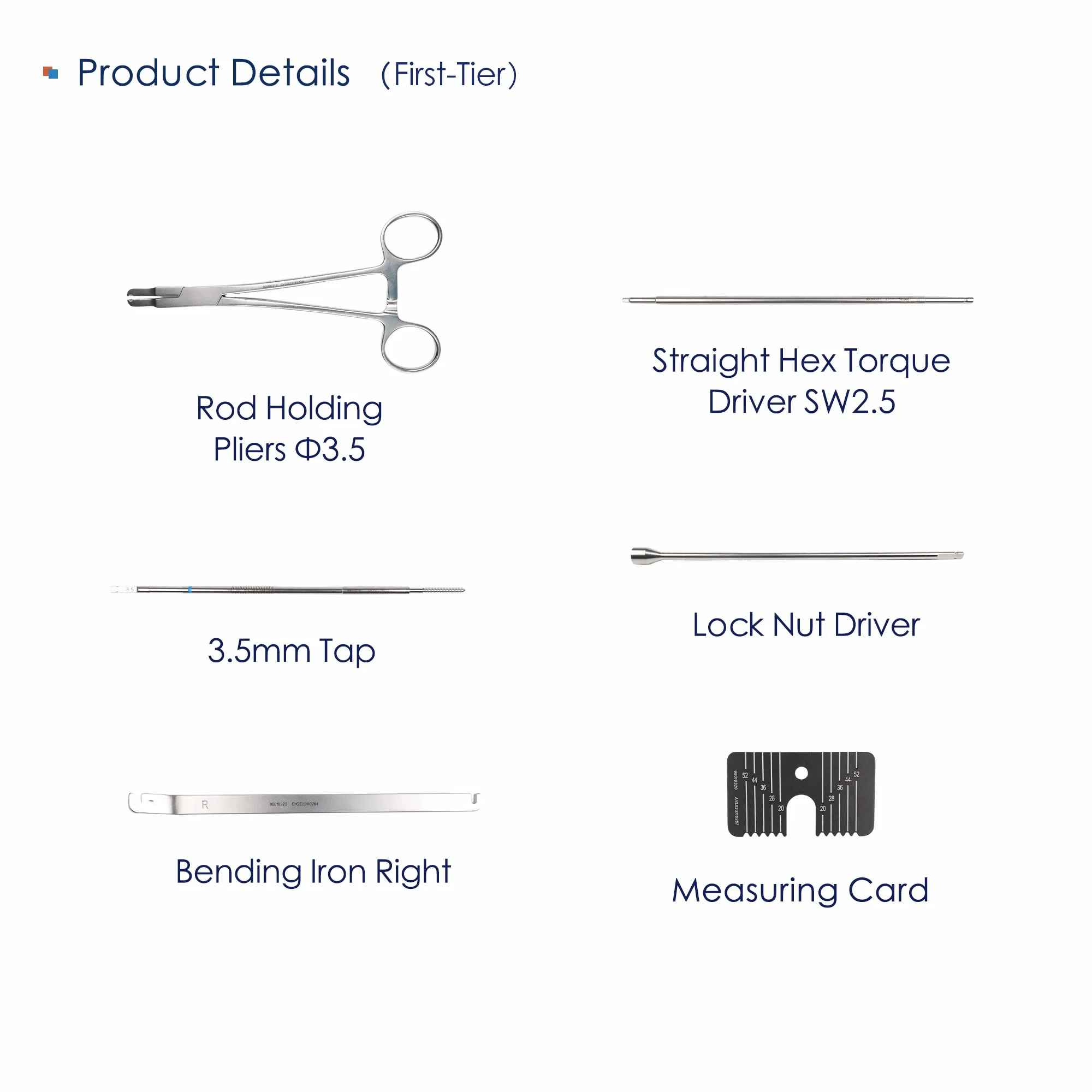
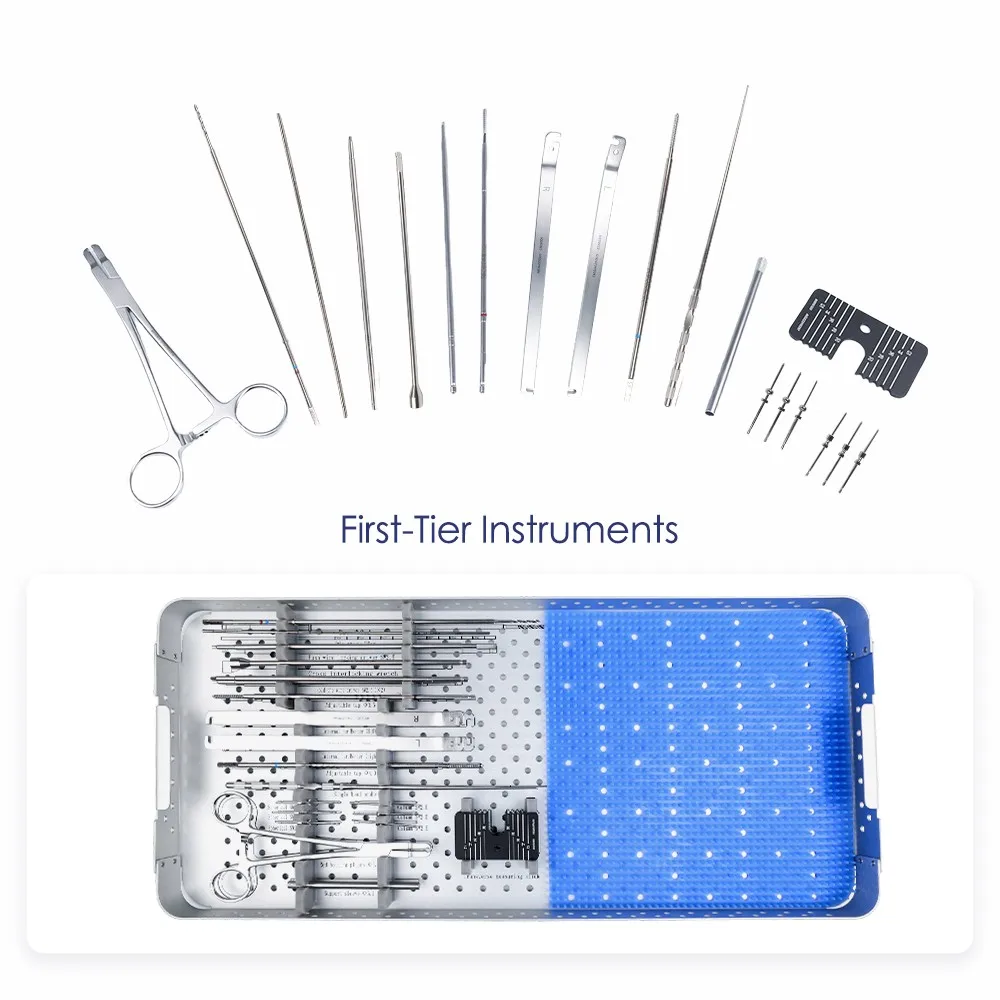
Complete Instrument List: 37 Line Items, 44 Pieces
The table below is the standard configuration of the posterior cervical screw-rod instrument set. Quantities are per set; item codes are Geasure catalogue codes and can be used directly for reordering or for building a hospital inventory record.
| No. | Instrument | Specification | Qty | Code |
|---|---|---|---|---|
| 1 | Open cone (bone awl) | Ø2.0 | 1 | 90011620 |
| 2 | Pedicle probe | Ø2.1 | 1 | 90010302 |
| 3 | Countersink reamer | — | 1 | 90010303 |
| 4 | Screwdriver, universal top-loading | SW2.5 | 2 | 90010304 |
| 5 | Cross-link hook holder | — | 1 | 90010305 |
| 6 | Reduction forceps | — | 1 | 90010306 |
| 7 | Drill guide, fixed | Ø4.1 | 1 | 90010307 |
| 8 | Drill guide, adjustable | Ø4.1 | 1 | 90010308 |
| 9 | Counter-torque sleeve wrench | — | 1 | 90010309 |
| 10 | Quick-change handle | — | 2 | 90011609 |
| 11 | Rod template | 240 mm | 1 | 90010310 |
| 12 | Rod cutter, ratcheting | — | 1 | 90010311 |
| 13 | Rod bender | — | 1 | 90010312 |
| 14 | Rod-holding forceps | Ø3.5 | 1 | 90010313 |
| 15 | Rod rotator, power grip | Ø3.5 | 1 | 90010314 |
| 16 | Rod cutter, low-profile (in situ) | — | 1 | 90010315 |
| 17 | Compression forceps, low-profile | — | 1 | 90010316 |
| 18 | Distractor forceps, low-profile | — | 1 | 90010317 |
| 19 | Set-screw driver | SW2.5 | 1 | 90010318 |
| 20 | Cross-link locking wrench | — | 1 | 90010319 |
| 21 | Cross-link measuring gauge | — | 1 | 90010320 |
| 22 | Set-screw holding driver | SW2.5 | 2 | 90010321 |
| 23 | Rod bender, in situ (left) | — | 1 | 90010322 |
| 24 | Rod bender, in situ (right) | — | 1 | 90010323 |
| 25 | Support sleeve | Ø5.1 | 1 | 90010324 |
| 26 | Orthopedic drill bit | Ø2.4 | 1 | 90010325 |
| 27 | Bone tap, adjustable | Ø3.5 | 1 | 90010326 |
| 28 | Bone tap, adjustable | Ø4.0 | 1 | 90010327 |
| 29 | Bone probe, single-ended | — | 1 | 90010328 |
| 30 | Guide pin, ball-end | SW2.5 | 3 | 90010329 |
| 31 | Guide pin, cylindrical | SW2.5 | 3 | 90010330 |
| 32 | Radiopaque pin inserter | SW2.5 | 1 | 90010331 |
| 33 | Depth gauge | — | 1 | 90010332 |
| 34 | Set-screw box | — | 1 | 90010333 |
| 35 | Screw box | — | 1 | 90010334 |
| 36 | Screw positioner | — | 1 | 90010335 |
| 37 | Instrument container | — | 1 | 90010336 |
| — | Total, standard configuration | 37 line items | 44 | — |
Tier 2 in Detail: Probe, Drill Guide, Tap and Reduction
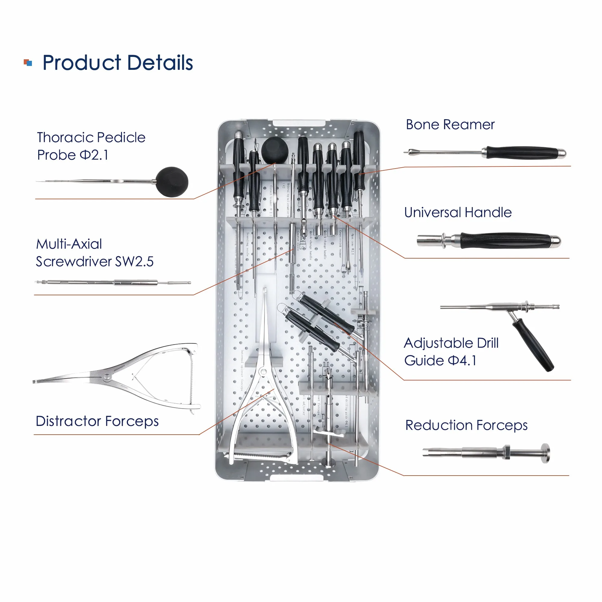
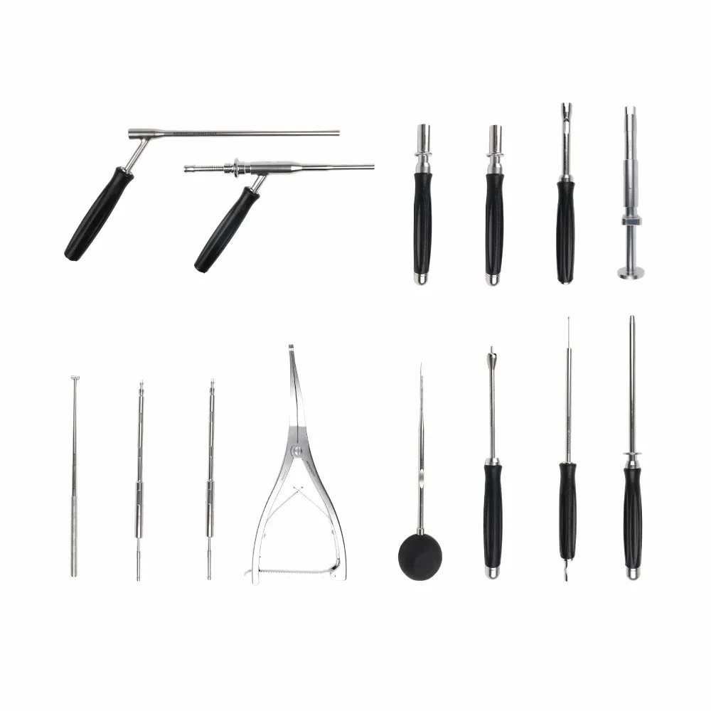
Tier 2 carries the instruments that decide screw accuracy. The Ø2.1 pedicle probe is used first to develop the track and to read cortical resistance; a Ø4.1 drill guide — fixed for a pre-planned trajectory, adjustable when the angle has to change intraoperatively — then constrains the Ø2.4 drill bit. A Ø5.1 support sleeve protects the surrounding soft tissue while the guide is held in place.
Threads are cut with the adjustable Ø3.5 or Ø4.0 tap, matching the two screw diameters of the implant system; the 240 mm rod template and the depth gauge confirm length before the implant is opened. After the rods are seated, reduction forceps, distractor forceps and compression forceps manage alignment and load, and the SW2.5 set-screw drivers lock the construct.
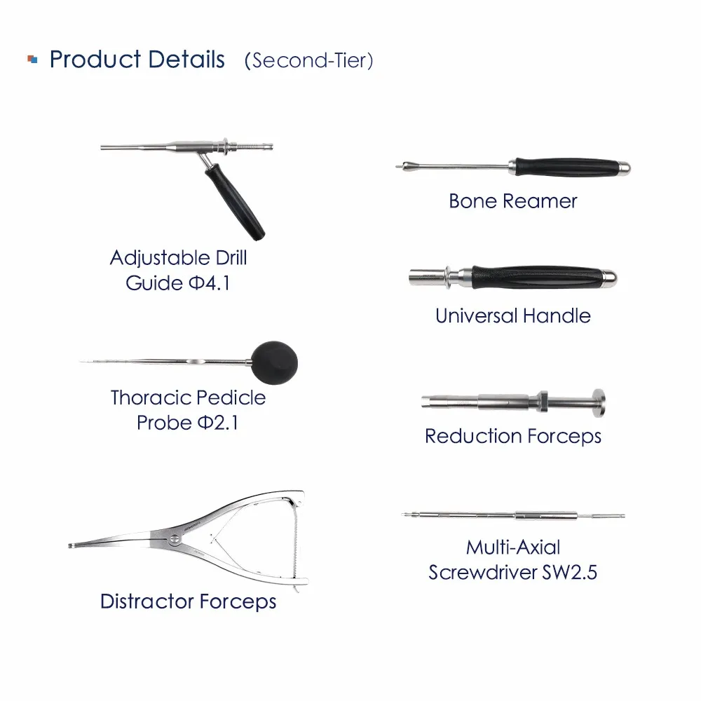
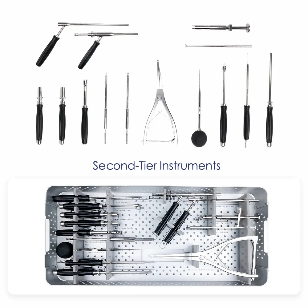
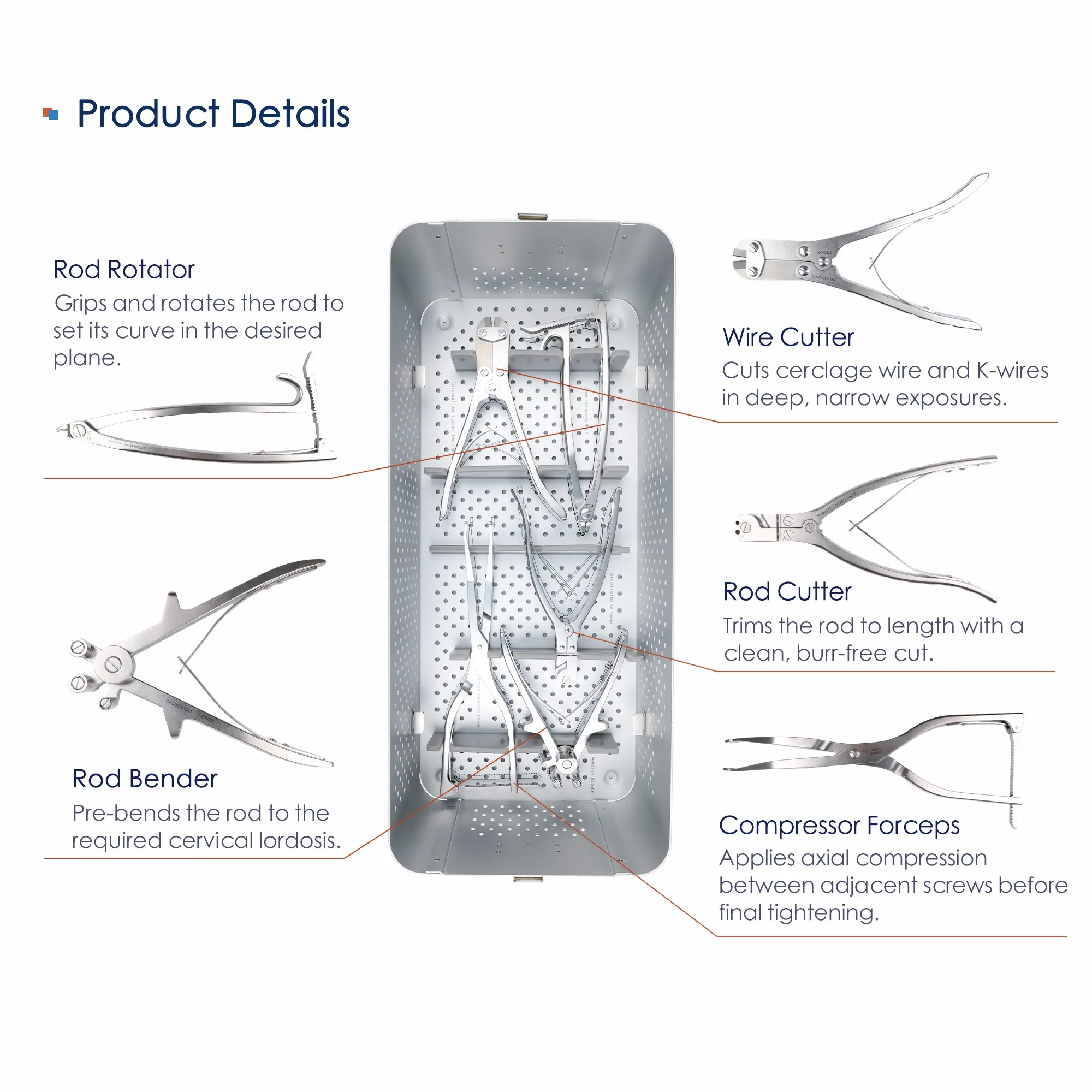
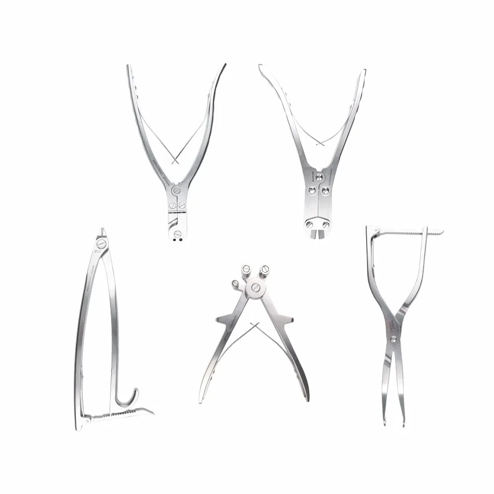
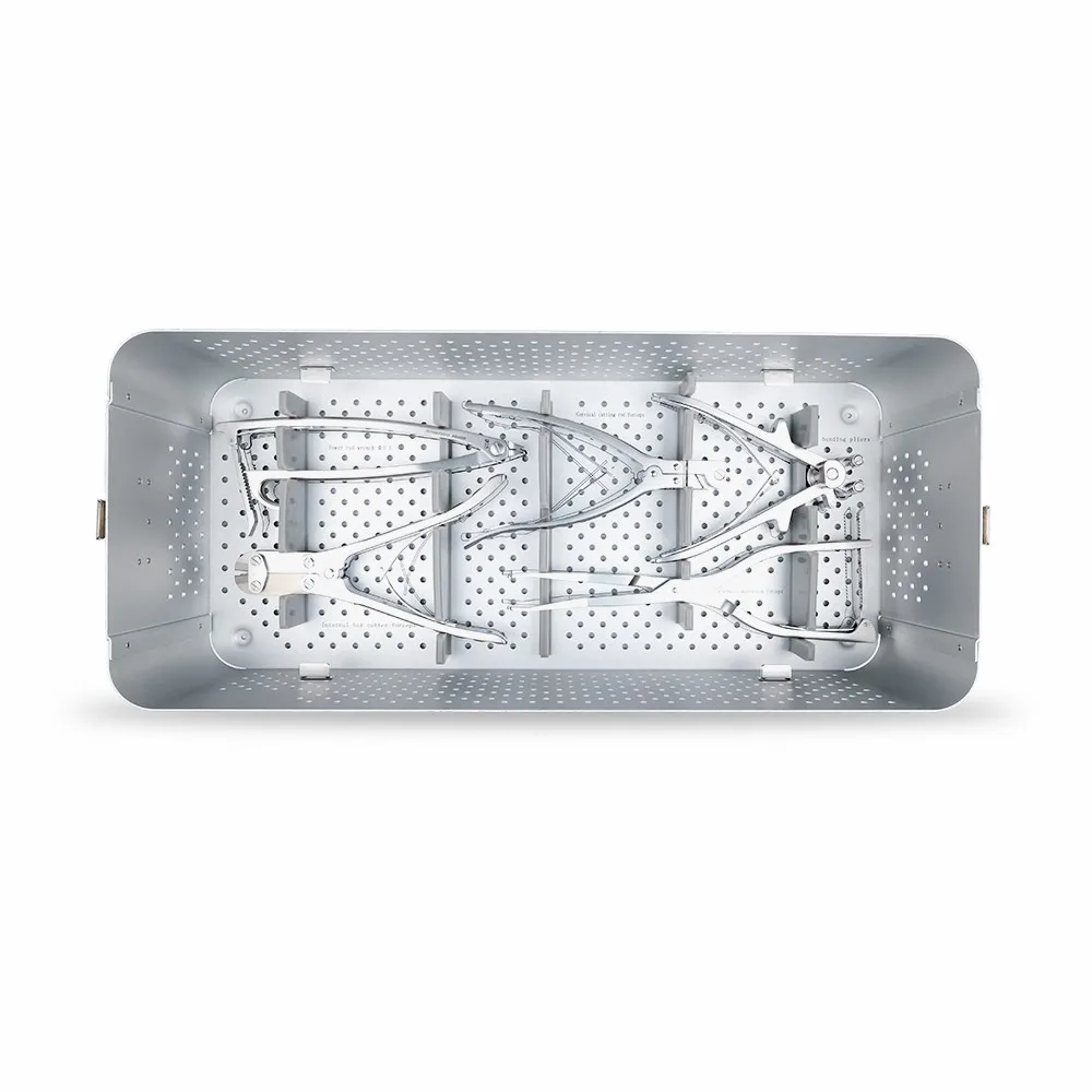
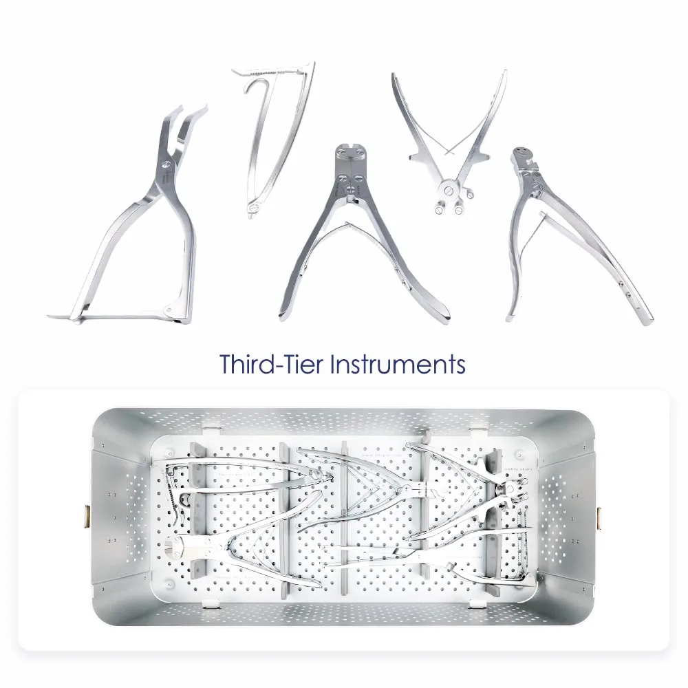
Tier 3 in Detail: Contouring, Cutting and Compression
Tier 3 holds the five forceps that shape and finish the construct. Rods are pre-bent with the rod bender, or bent in situ with the left and right in-situ benders when the rod is already seated; the Ø3.5 rod rotator then rotates the bent section into the desired plane without levering against the screw heads.
Cutting is split by working space: the ratcheting rod cutter is used where access allows a full stroke, while the low-profile in-situ cutter trims the rod inside the wound. Compression forceps apply axial load between adjacent screws before the set screws are finally tightened, and the reduction forceps correct residual offset.
- Bend, then rotate: two separate instruments keep curvature and plane independent.
- Cut where you are: ratcheting for the back table, low-profile for in situ trimming.
- Compress before locking: axial load is applied while the set screw is still free.
Six Surgical Steps, One Instrument Set
The sequence below maps each stage of a posterior cervical screw-rod procedure to the instruments that support it, with the packing-list item numbers for cross-reference.
Entry and trajectory
Open cone (No. 1) marks the entry; pedicle probe (No. 2) develops and checks the track; bone probe (No. 29) confirms the walls.
Drill and tap
Ø2.4 bit (No. 26) through a fixed or adjustable Ø4.1 guide (No. 7–8), then Ø3.5 or Ø4.0 tap (No. 27–28).
Screw insertion
SW2.5 universal screwdriver (No. 4) seats the polyaxial screws; guide pins (No. 30–31) hold the level if needed.
Rod contouring and seating
Rod bender (No. 13) or in-situ benders (No. 23–24), rod rotator (No. 15), rod-holding forceps (No. 14).
Reduction and compression
Reduction forceps (No. 6), distractor forceps (No. 18), compression forceps (No. 17) set the final alignment.
Lock and finish
Set-screw drivers (No. 19, 22) with counter-torque sleeve (No. 9); rod cutters (No. 12, 16) trim the ends; cross-link wrenches (No. 20) close the construct.
Full Instrument Gallery, Tray by Tray
Complete tray contents for pre-operative counting, configuration review and staff training.
Four Details That Decide How the Set Performs in the OR
Sequence-based layout
Three trays follow the three phases of the procedure. The scrub nurse works from one tray at a time instead of searching a single mixed case.
One driver interface
SW2.5 covers screw insertion, set-screw driving and holding. Fewer interfaces means fewer changeovers and fewer mismatched parts on the field.
Diameters aligned to the implant
Taps at Ø3.5 and Ø4.0, a Ø2.4 drill and Ø4.1 guides are sized to the implant screw range, so one set covers both screw diameters.
Container and sterilization in one
Perforated metal container with silicone cradles and dividers: cleaning, drying, sterilization and transport without repacking.
Indications, Reprocessing and Maintenance
The set supports posterior cervical and upper thoracic screw-rod fixation in the indications covered by the matching implant system: cervical instability, cervical spondylosis with myelopathy, cervical stenosis requiring stabilization after decompression, cervical trauma and fractures, and cervical deformity correction.
- Posterior lateral mass and pedicle screw-rod fixation
- Stabilization after posterior decompression
- Posterior reduction and fixation in trauma or dislocation
- Revision procedures requiring implant removal and reinsertion
Reprocessing follows the hospital's standard instrument workflow: remove blood and bone debris, clean the tray cavities — preferably with ultrasonic support — dry, reassemble tray by tray, and sterilize in the perforated container. Store forceps with jaws closed and tips protected; inspect cradles and jaw alignment at each reprocessing cycle.
Frequently Asked Questions
Short answers to the questions distributors and hospital procurement teams ask most often about this set.
What is included in the posterior cervical screw-rod instrument set?
The standard configuration contains 37 line items and 44 pieces, including probes, drill guides, taps, screwdrivers, rod benders, rod cutters, reduction and compression forceps, cross-link instruments, two implant boxes and one instrument container, supplied in three perforated trays.
Which implant system is it designed for?
It is the matching instrument set for the Geasure posterior cervical screw-rod fixation system: Ø3.5 mm and Ø4.0 mm polyaxial screws, Ø3.5 mm connecting rods, M6 set screws and a Ø3.5 mm plate-clamp cross-link.
What is the difference between the fixed and the adjustable drill guide?
The fixed Ø4.1 guide repeats a pre-planned trajectory, which suits multi-level fixation at a consistent angle. The adjustable Ø4.1 guide allows the drilling angle to be changed intraoperatively, for example when moving between lateral mass and pedicle trajectories.
Is the set reusable, and how is it sterilized?
Yes, the instruments are reusable. They ship in a perforated metal container that can go through the full cleaning, drying and steam sterilization cycle; follow the validated cycle of your facility and inspect the instruments after each use.
Can the configuration be customized?
Yes. Tray layout, instrument selection, laser marking, packaging and documentation can be configured for OEM/ODM projects. Share the surgical routine and target market so the proposed configuration can be checked for feasibility before quotation.
Can it be combined with implants from another manufacturer?
No cross-brand compatibility is implied. Instruments and implants are validated as one Geasure system; confirm dimensions and compatibility in writing before combining components from different sources.
Which documents are available for procurement?
Packing list with item codes, specification sheet, and material or inspection documents on request. Regulatory documents are provided for the specific product and target market, subject to current validity.
Ordering, OEM/ODM and Documentation
The set is supplied as a complete tray system. Distributors can order the standard configuration or a project-specific configuration built around a surgical routine; both are quoted against the confirmed packing list, marking and packaging requirements.
- Standard configuration: 37 line items, 44 pieces, three trays and one perforated container
- Project options: instrument add/remove, tray layout, laser marking, packaging and labelling
- Documentation: packing list, specification sheet, inspection and regulatory documents as applicable
For the implant side of the system, see the posterior cervical screw-rod fixation system. Related instrument families are listed under spine instruments and spine implants.
Planning a cervical fixation project?
Send the screw diameters, rod lengths, cross-link spans and the target market. We will return a matched instrument configuration, packing list and documentation scope.
View the matching implant systemPage last reviewed: November 2026. Instrument names, quantities and codes follow the current Geasure packing list; specifications are subject to change without notice.