



-
Geasure Medical
-
1
-
ISO 13485 \ CE \ FDA 510(k) Cleared \ Free Sale Certificate\ MDSAP
-
Stainless steel
-
Custom service supported
-
7–14 Days (OEM: 15–30 Days)
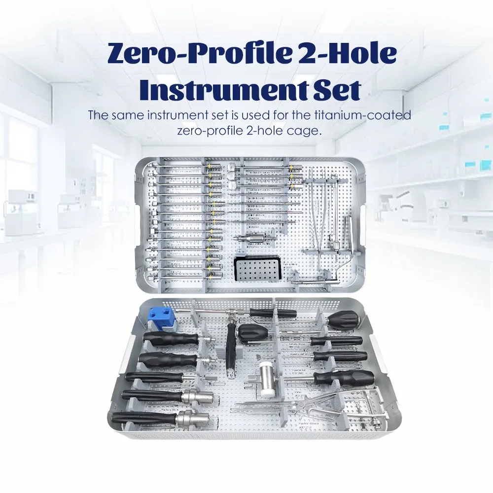
Zero-Profile 2-Hole Cervical Cage Instrument Set for ACDF
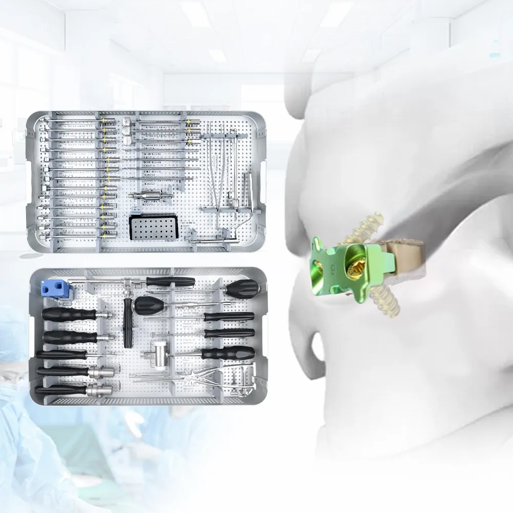
The zero-profile 2-hole cervical cage instrument set is a two-tier reusable surgical instrument system for trialing, preparing, packing, inserting and locking a two-screw integrated cervical interbody cage during anterior cervical discectomy and fusion (ACDF).
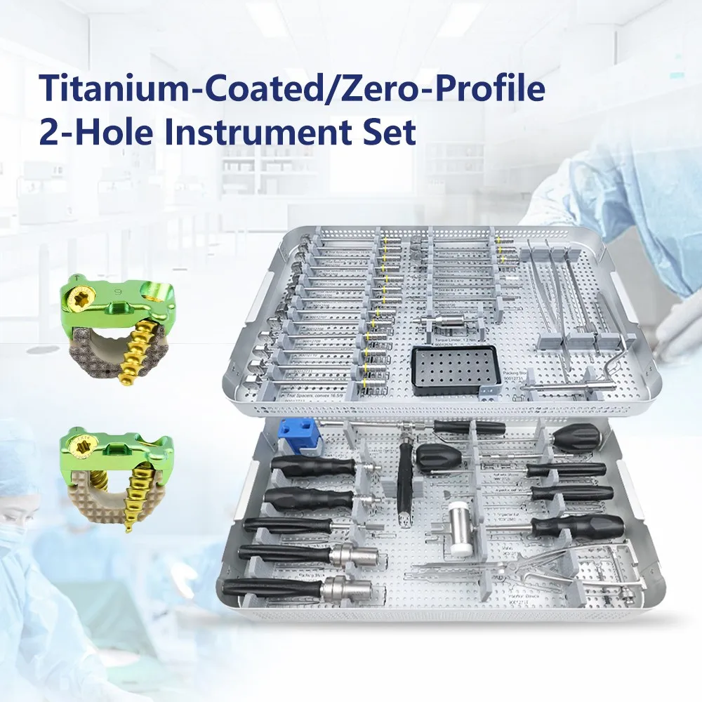
It supports the titanium-coated zero-profile 2-hole cage shown in the product visuals. The first tier brings trial spacers, depth-controlled drills and implant preparation tools together; the second tier carries awls, drivers, impactors, a mallet, insertion instruments and quick-connect handles. The layout follows the operative sequence so each tool can be located and counted without mixing stages.
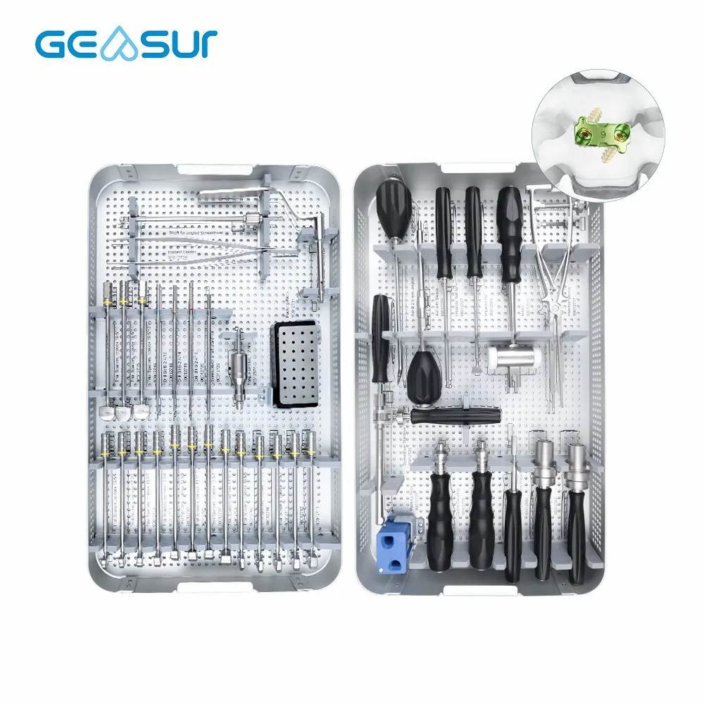
One Instrument Set for the Titanium-Coated 2-Hole Cage
The set is designed around one implant workflow: a zero-profile cervical interbody cage with two integrated screw trajectories. Trial spacers reproduce the cage footprint and height during sizing; depth-controlled drills and awls prepare the screw paths; inserters carry the cage; and the 1.2 Nm torque limiter supports repeatable final locking.
Trial before opening
Multiple convex trial spacers allow footprint and height to be checked before the implant package is opened.
Controlled screw paths
Depth-marked Ø2.4 drills, straight and angled awls, sleeves and guides support repeatable trajectory preparation.
Torque-controlled finish
The marked 1.2 Nm torque limiter provides a defined end point for the final locking step.
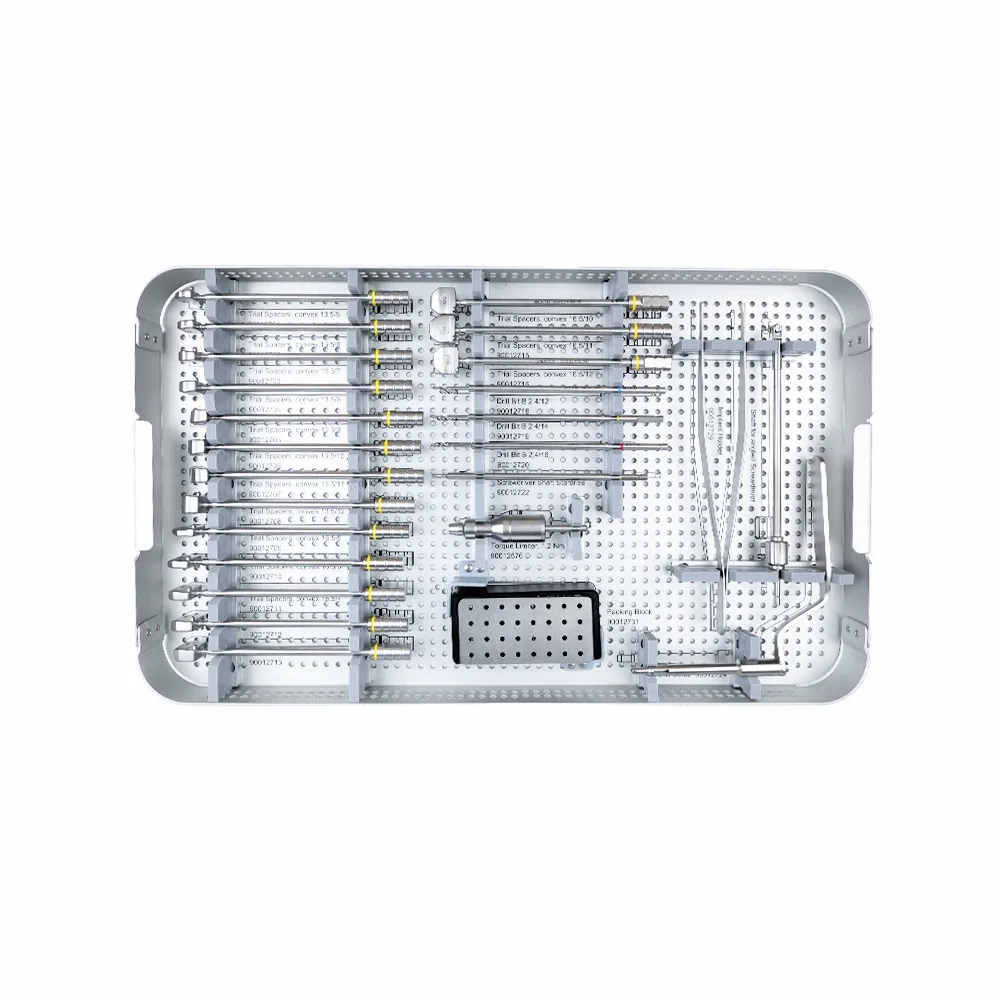
First Tier: Trialing, Drilling and Implant Preparation
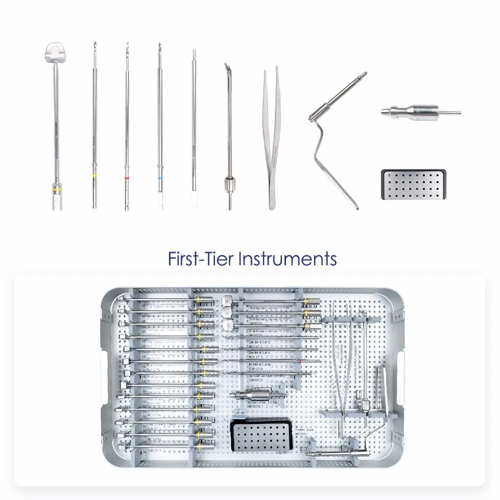
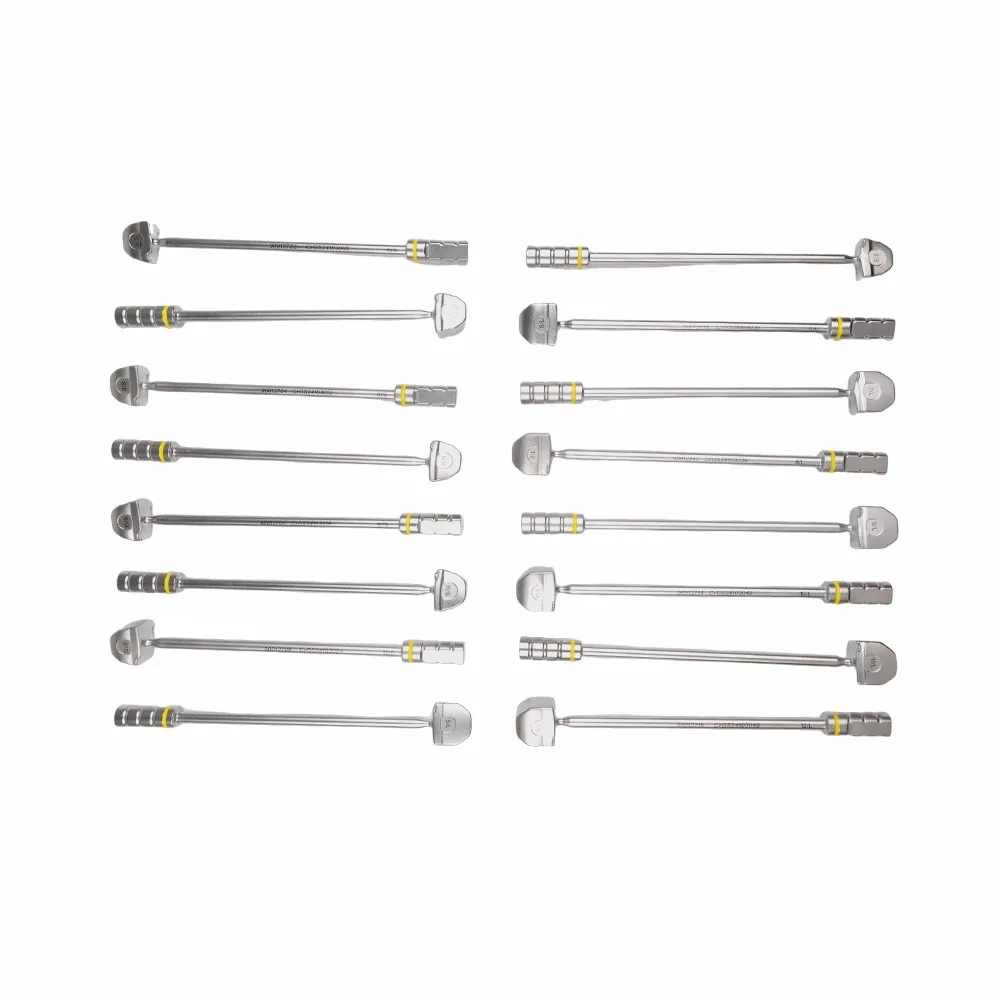
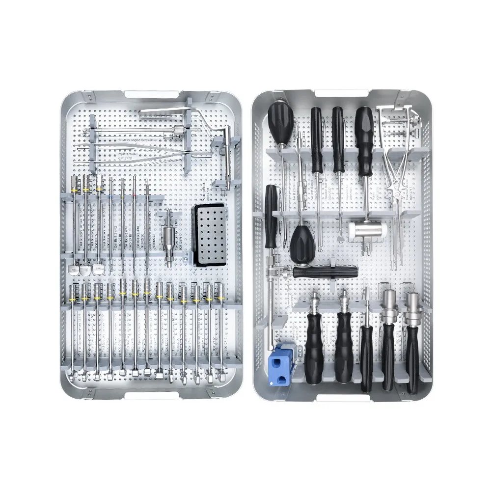
The first tier is the sizing and preparation layer. Rows of convex trial spacers are organized by footprint and height, making adjacent sizes easy to compare while the disc space is held open. Color rings on the shafts provide a second visual cue during exchange.
The same tray carries the Ø2.4 drill family, including the clearly marked 12 mm, 14 mm and 18 mm depth options visible in the supplied images. A screwdriver shaft system, 1.2 Nm torque limiter, implant loading or packing block, forceps and insertion accessories complete the transition from trial to implant.
- Trial spacers: convex profiles in multiple footprints and heights for disc-space sizing.
- Depth-marked drills: Ø2.4 shafts for controlled screw-path preparation.
- Torque limiter: engraved 1.2 Nm limiter for the final locking step.
- Loading and handling: packing block, holder and forceps keep the implant controlled before insertion.
Second Tier: Awls, Drivers, Impactors and Insertion Instruments
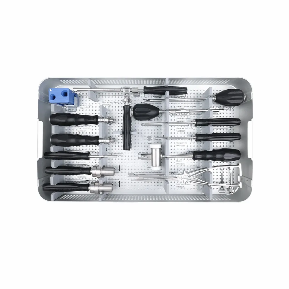
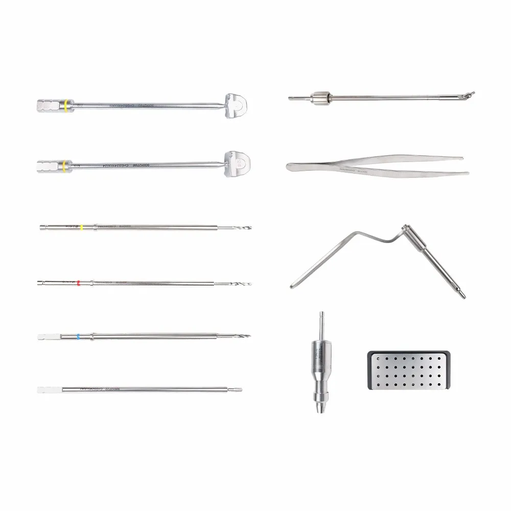
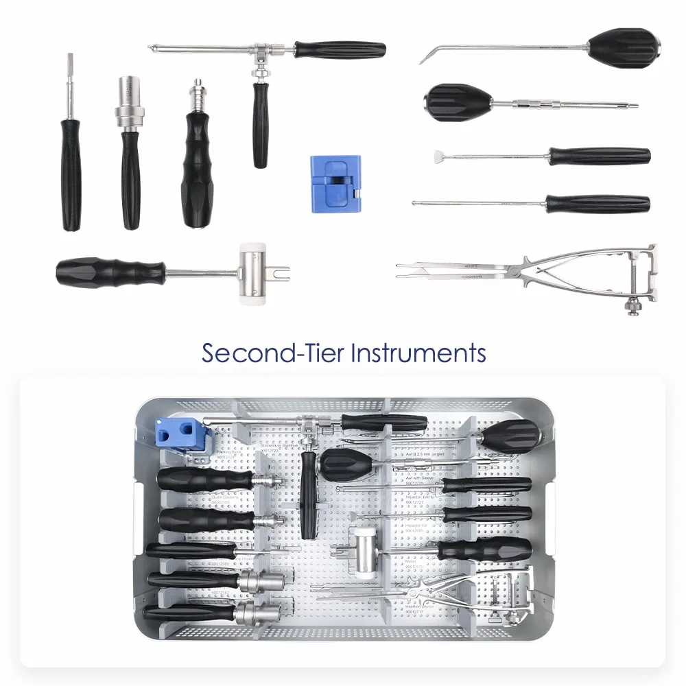
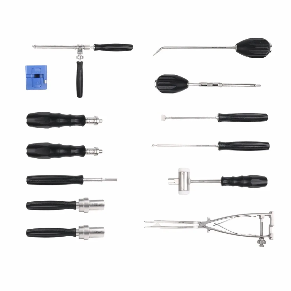
The second tier is the access and delivery layer. It contains the instruments that prepare the two integrated screw paths and move the cage from holder to final position. Visible engravings identify a 2.5 mm angled awl, an awl with sleeve, flat impactors, a mallet, insertion device and quick-connect couplings.
Separating handled instruments from the long trial and drill shafts prevents overlap in the case. The open layout also exposes the working tips for inspection after cleaning while keeping the handles aligned for rapid assembly.
- Pathway opening: angled 2.5 mm awl and sleeved awl provide two preparation options.
- Impact and seating: flat impactor and mallet support controlled advancement.
- Insertion: the insertion device maintains cage orientation during delivery.
- Modular assembly: quick-connect handles and couplings reduce the number of complete fixed instruments.
Functional Instrument Groups
The exact standard configuration is defined by the confirmed packing list. From the supplied product images, the set can be organized into the following functional groups without assuming specifications that are not legible.
| Instrument group | Visible components | Role in the procedure |
|---|---|---|
| Trialing | Multiple convex trial spacers in graduated sizes | Evaluate footprint, height and fit before selecting the implant. |
| Disc-space preparation | Straight and angled preparation shafts, packing block and forceps | Prepare the working space and control implant filling or handling. |
| Drilling | Ø2.4 drills; visible 12, 14 and 18 mm markings; guides and sleeves | Prepare two screw paths while controlling trajectory and depth. |
| Awling | 2.5 mm angled awl and awl with sleeve | Open the screw path where the surgeon selects an awl-led workflow. |
| Insertion | Insertion device, implant holder, flat impactors and mallet | Deliver, orient and seat the cage while maintaining control. |
| Screwdriving | Screwdriver shaft system, modular handles and quick couplings | Insert and adjust the integrated screws. |
| Final locking | Torque limiter marked 1.2 Nm | Provide a defined end point for the final screw-locking step. |
| Storage | Two perforated trays and labeled retention brackets | Support cleaning, sterilization, transfer, visual inspection and counting. |
From Trialing to Final Locking in Six Steps
The two trays map to a concise ACDF workflow: size the disc space, prepare the implant and screw paths, insert the cage, seat it and finish with controlled locking.
Prepare the disc space
Complete decompression and preserve the bony endplates according to the paired implant's surgical technique.
Trial the footprint and height
Insert sequential convex trials until the implant footprint and restored height are confirmed.
Prepare the cage
Load the selected cage, pack graft material as required and connect the holder or inserter.
Insert and seat
Advance the cage under imaging control; use the impactor and mallet only as described in the IFU.
Prepare two screw paths
Select the drill-and-guide or awl-and-sleeve workflow and create the two integrated trajectories.
Insert and lock
Drive the screws and complete final locking with the 1.2 Nm torque limiter; verify position radiographically.
Two Trays for Reprocessing, Transfer and Fast Counting
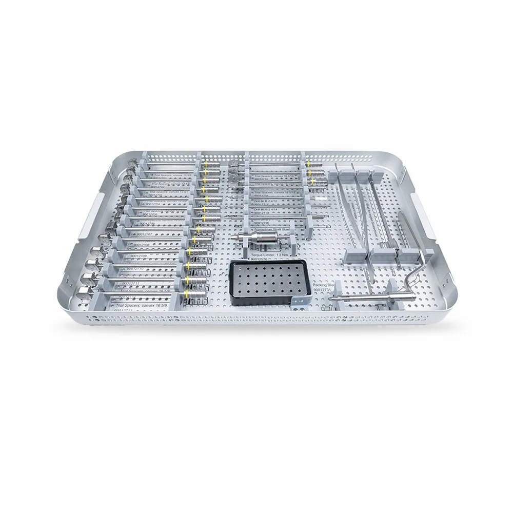
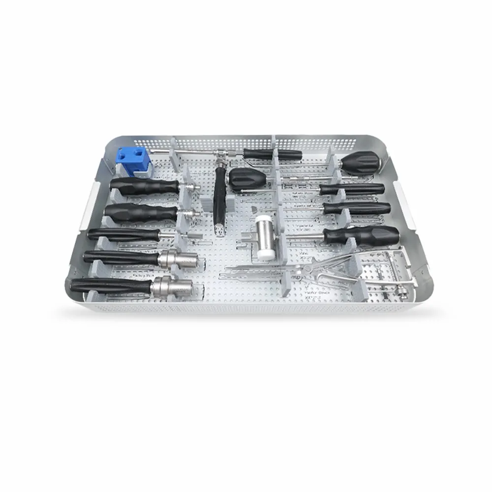
Both layers use perforated stainless-steel-style trays with open walls, a perforated base and dedicated retention brackets. The format keeps the working ends exposed for visual inspection and allows fluid and steam to reach the instruments during validated reprocessing.
- One assigned location per instrument supports pre-operative and post-operative counting.
- Open perforations support the validated cleaning, drying and steam-sterilization workflow.
- Silicone and metal retainers separate instruments and protect working ends during transfer.
- Tray-level separation keeps trial and drill shafts apart from the handled insertion tools.
- Visible markings allow trial, drill and torque specifications to be checked before use.
Frequently Asked Questions
Direct answers for distributors, procurement teams and surgical staff evaluating the two-hole zero-profile cervical cage instrumentation.
What is the zero-profile 2-hole cervical cage instrument set?
It is a two-tier reusable instrument system used to trial, prepare, insert and lock an integrated two-screw cervical interbody cage during ACDF.
Which implant does the set support?
It is designed for the titanium-coated zero-profile 2-hole cervical cage shown in the supplied product images. Compatibility with another manufacturer or implant family should not be assumed.
What is included in the first tier?
The first tier contains multiple convex trial spacers, Ø2.4 depth-marked drills, a screwdriver shaft system, a 1.2 Nm torque limiter, a packing or loading block, forceps and insertion accessories.
What is included in the second tier?
The second tier contains the angled 2.5 mm awl, awl with sleeve, flat impactors, mallet, modular handles and couplings, insertion device and other handled preparation instruments visible in the tray.
Does the set support both drill and awl workflows?
Yes. The supplied configuration includes depth-marked drills with guides and sleeves as well as straight or angled awl options. The selected sequence must follow the paired implant's surgical technique.
Why is a torque limiter included?
The limiter is marked 1.2 Nm and provides a defined end point for the final integrated-screw locking step when used according to the surgical technique.
Can the configuration be customized?
Tray layout, instrument selection, marking, packaging and documentation may be reviewed for OEM or ODM projects. The final proposal depends on the implant configuration and target market.
Configuration, Documentation and OEM Support
The instrument set is quoted against the paired implant configuration and a confirmed packing list. To evaluate a standard or private-label project, provide the implant size range, screw configuration, target market, expected annual volume and documentation requirements.
- Configuration: two tray levels, trial range, drill depths, awl options, insertion and locking tools
- Customization: instrument selection, tray layout, laser marking, packaging and labels
- Documentation: packing list, specification sheet, reprocessing instructions and market-specific files as applicable
Page last reviewed: November 2026. Product images and visible engravings are the source for the specifications stated on this page. Confirm final quantities, codes, materials and regulatory scope against current controlled documents before publication or ordering.


