



-
Geasure Medical
-
1
-
ISO 13485 \ CE \ FDA 510(k) Cleared \ Free Sale Certificate\ MDSAP
-
Stainless steel
-
Custom service supported
-
7–14 Days (OEM: 15–30 Days)
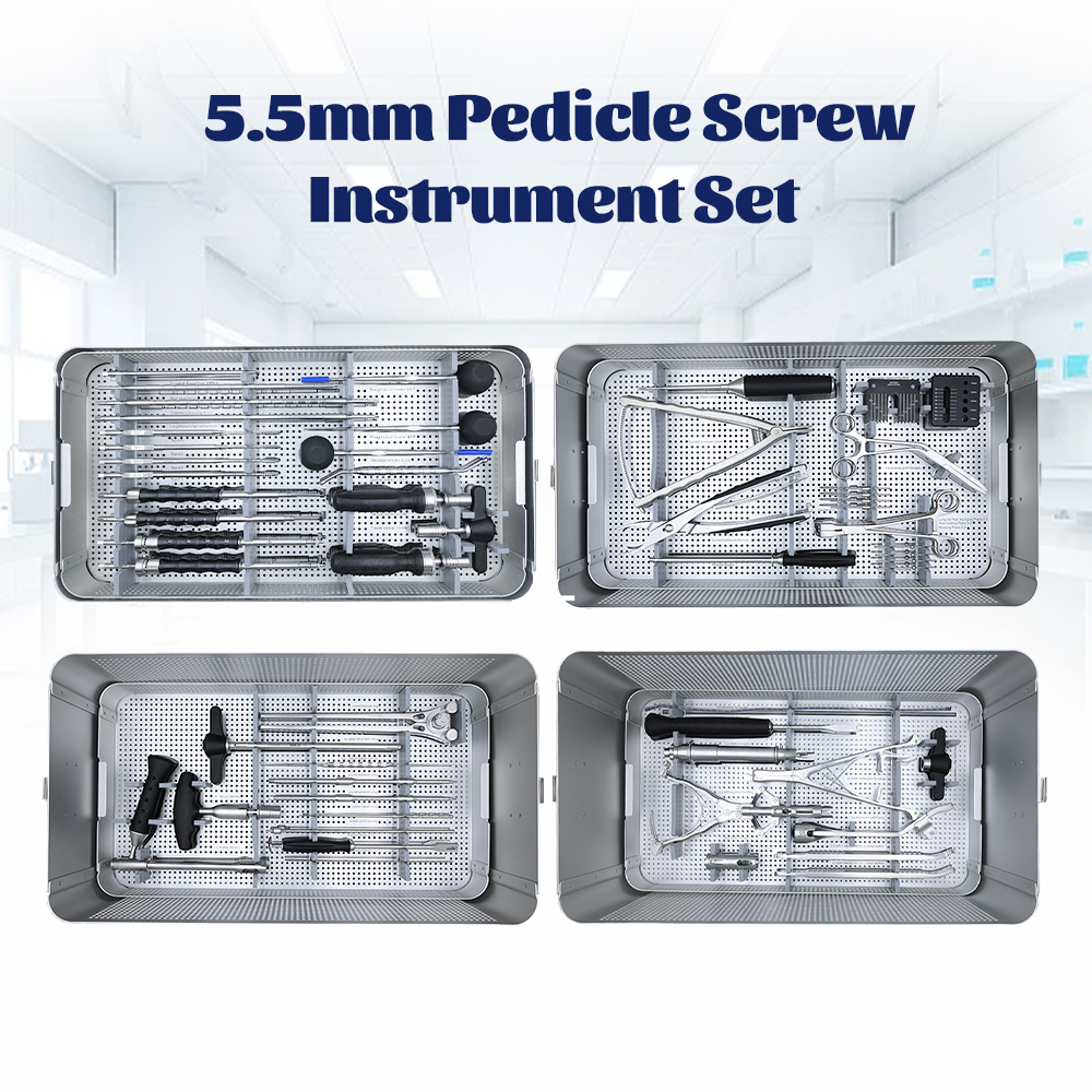
Four stacked trays, 51 coded lines, one perforated sterilization container. Photographed on production units.
A 5.5 Pedicle Screw Instrument Set Built Around Four Trays
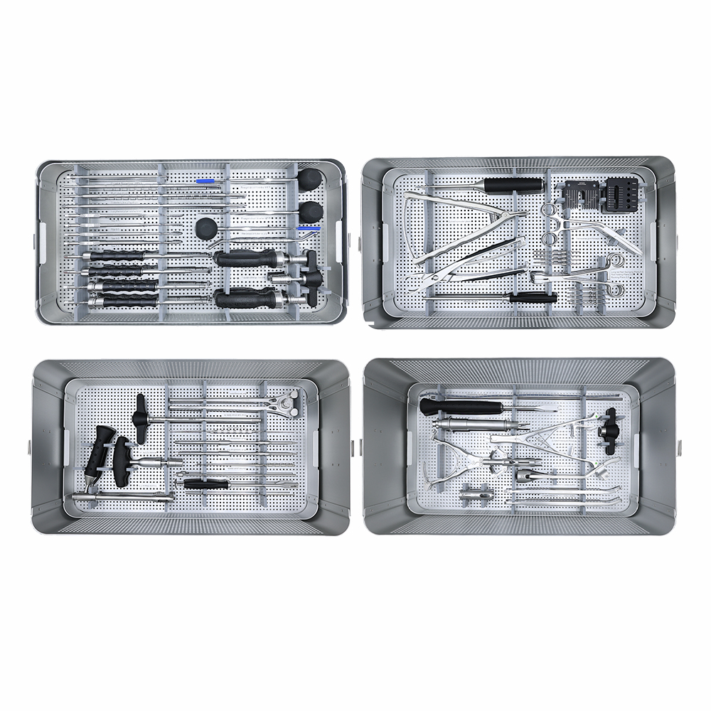
The 5.5 Pedicle Screw Instrument Set is a 50-instrument set, 59 pieces in total, for posterior thoracolumbar pedicle screw fixation with Ø5.5 mm rods. It is listed across 51 coded lines and packed in four stacked trays inside one perforated sterilization container. It covers the full working sequence: pedicle localization, tract preparation, tapping, screw delivery, rod contouring, reduction and final locking.
Each instrument carries its own code and sits in a fixed position. The tray floor is laser-marked, so a scrub nurse can check a tray against the schedule without lifting instruments out of their brackets.
The kit ships without implants. Screws, rods, set screws and cross connectors come from the matching 5.5 Pedicle Screw System, ordered separately against the case mix.
One Container, Four Trays, No Loose Instruments
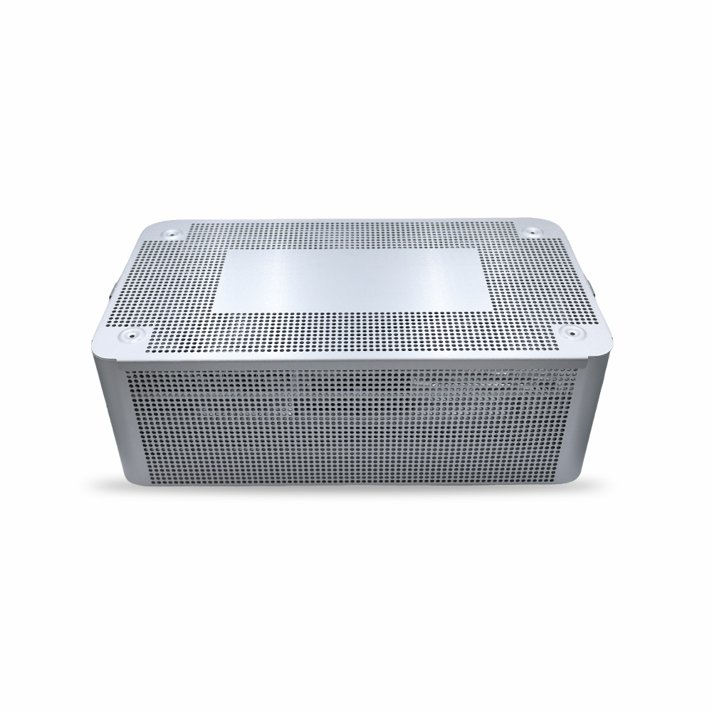
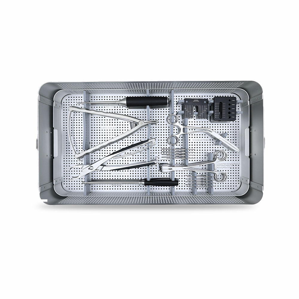
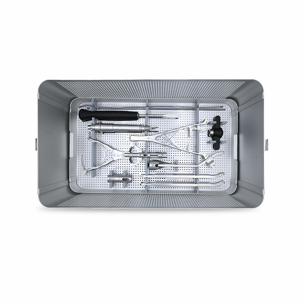
The set lives in a single perforated container with a removable lid and four stacking trays. Perforations run across the lid and all four side walls, and every tray is perforated as well, so the sterilant reaches both faces of each instrument rather than only the top layer.
Stacking order follows the procedure, not the alphabet. Tray 1 holds access and tapping, tray 2 measurement and rod work, tray 3 the long cannulated drivers and reduction, tray 4 rod insertion and final locking. A circulating nurse can pull one tray at a time onto the back table and leave the rest closed.
Each instrument sits in its own bracket, held at the shaft or the handle, with a slot of its own.
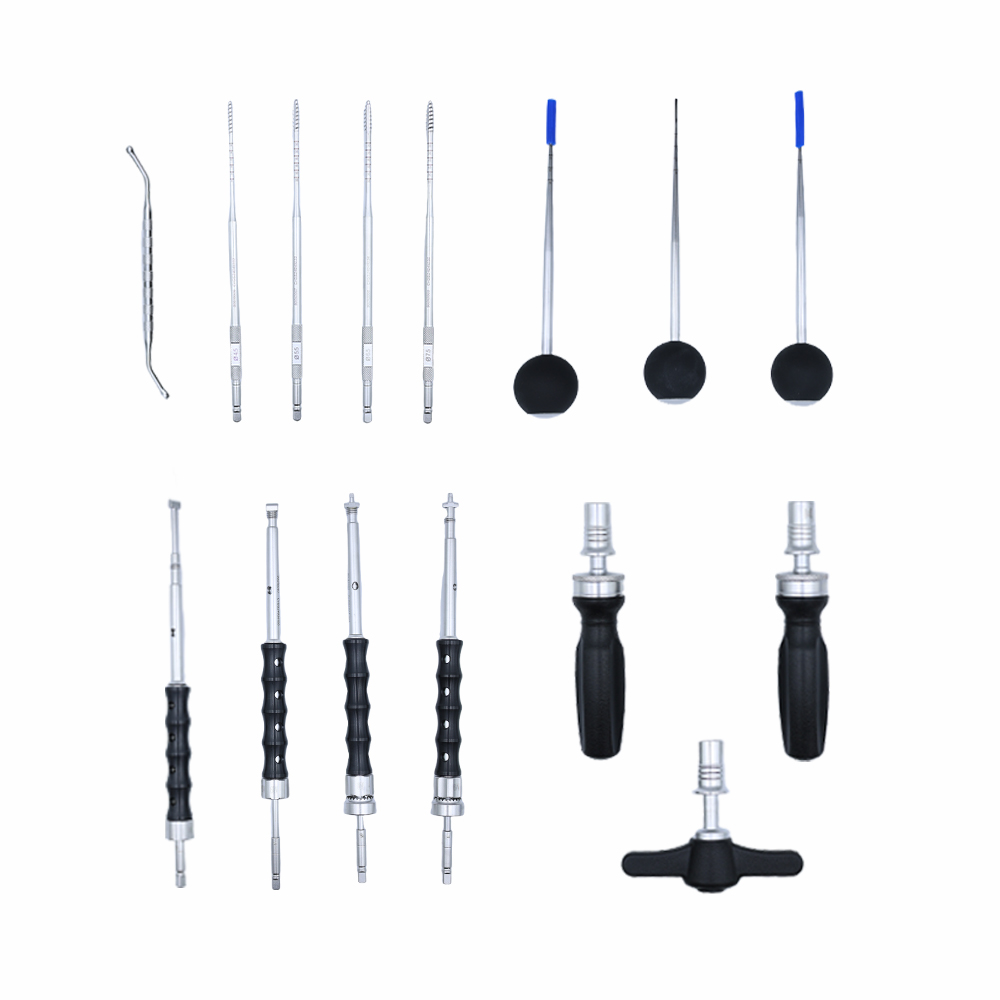
Tray 1: Access, Tapping and Screw Delivery
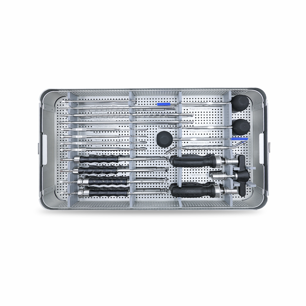
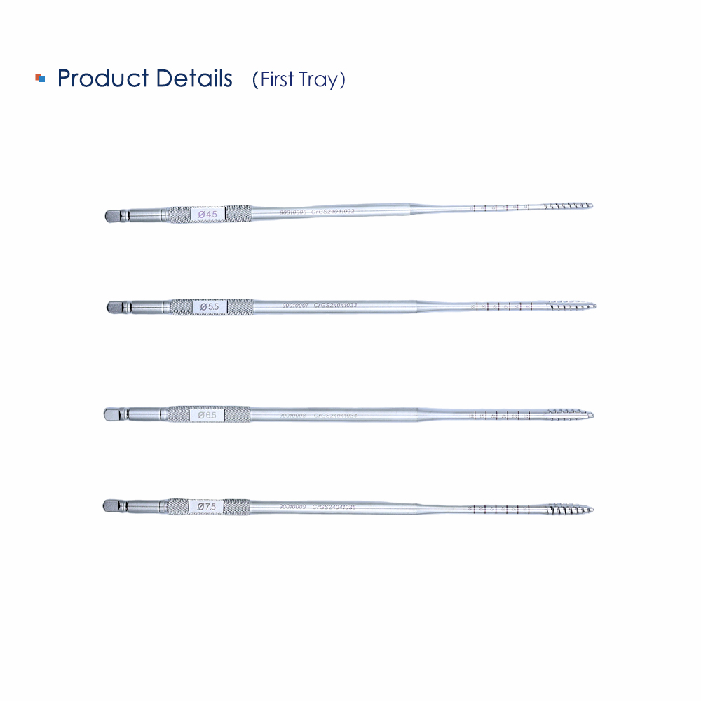
Tray 1 is the tray that opens the pedicle. It carries the open cone, three circuit breakers at Ø2.5, Ø3.2 and Ø3.5 mm, and four thread taps marked Ø4.5, Ø5.5, Ø6.5 and Ø7.5 on the shaft.
Each tap carries its diameter on the shaft collar, so it can be identified after it leaves its slot: the four taps look almost identical at arm's length under operating-room lighting.
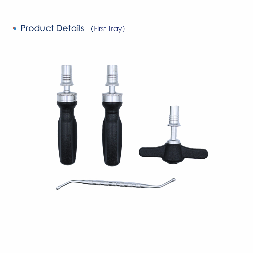
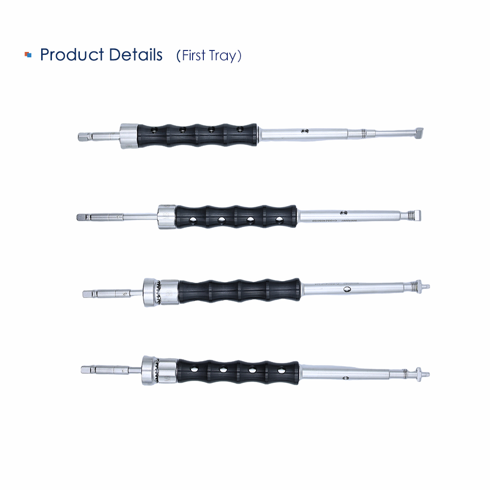
For delivery, the tray holds the universal M9 driver, the single-spindle M9 driver and two quick-load handles. The T quick-change handle and a spinner wrench SW4.0 complete it.
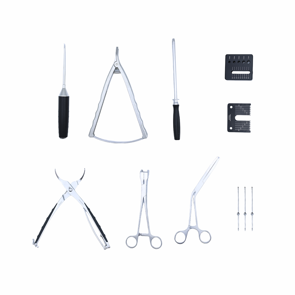
Tray 2: Exposure, Measurement and Rod Contouring
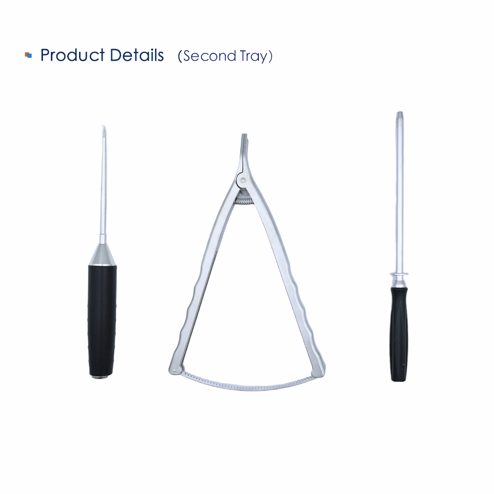
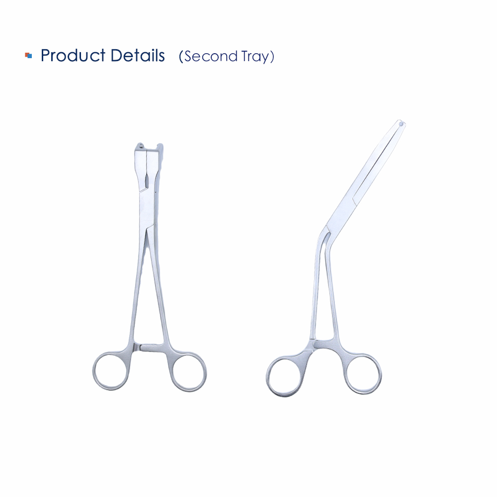
Tray 2 is the measuring tray. A depth gauge, a compass-type caliper and two black sizing templates sit beside the rod benders and cutters. The templates are the quickest check on screw diameter and rod length before anything is opened.
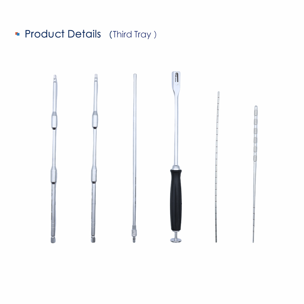
Tray 3: Cannulated Drivers and Reduction
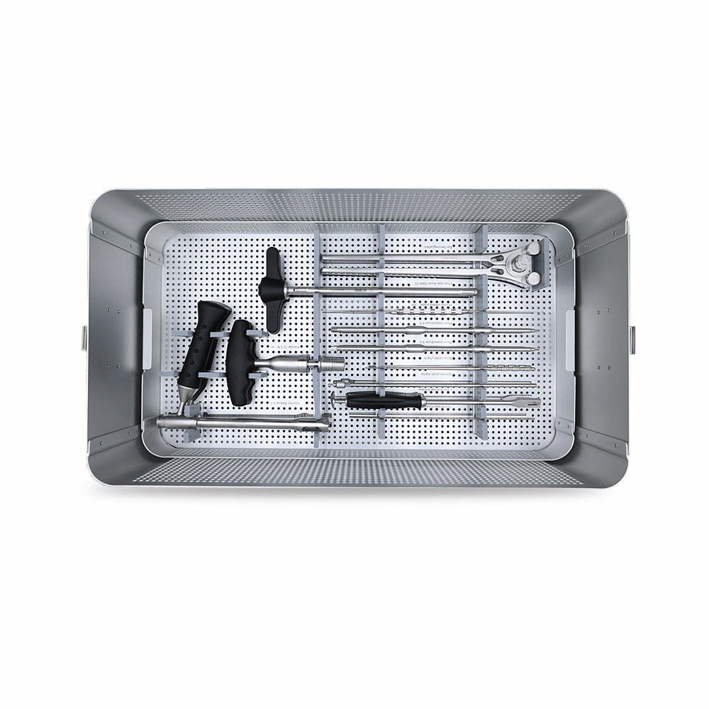
Tray 3 holds the long-reach instruments. Two cannulated drivers with sliding sleeves, a straight driver, a graduated depth gauge and the forked persuader all sit here, together with the T-handles that drive them.
The persuader seats a rod that will not drop into the screw head. Its fork fits over the head from above, and the T-handle applies load along the screw axis rather than levering against the adjacent level.
The tray carries two 5.5 screwdrivers, so a second one is on hand when the first comes out for cleaning.
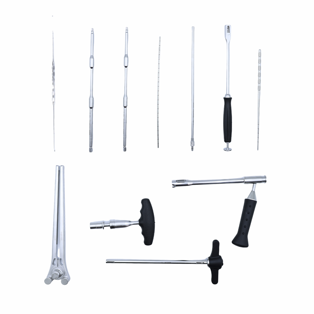
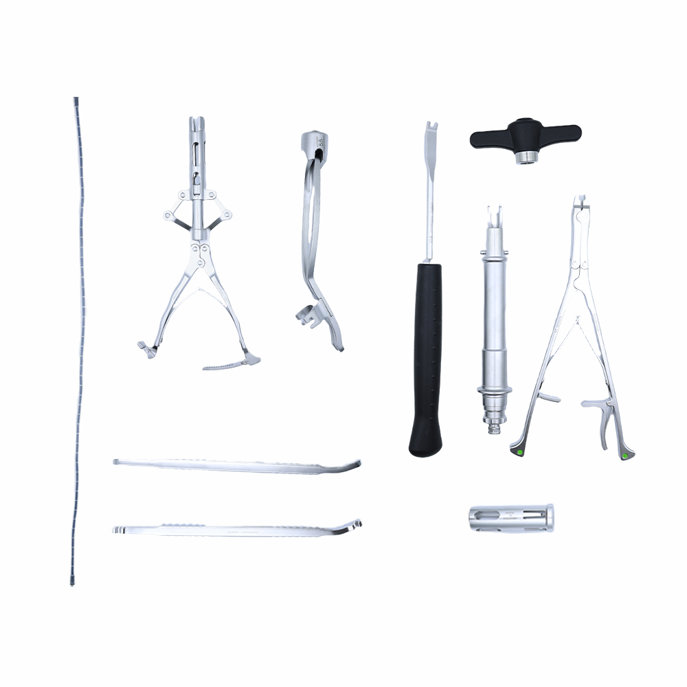
Tray 4: Rod Insertion and Final Locking
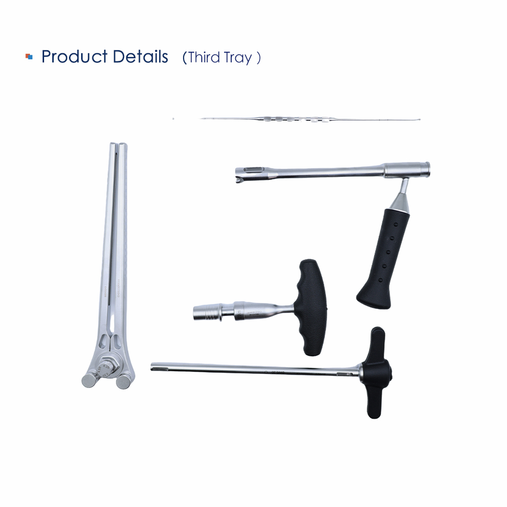
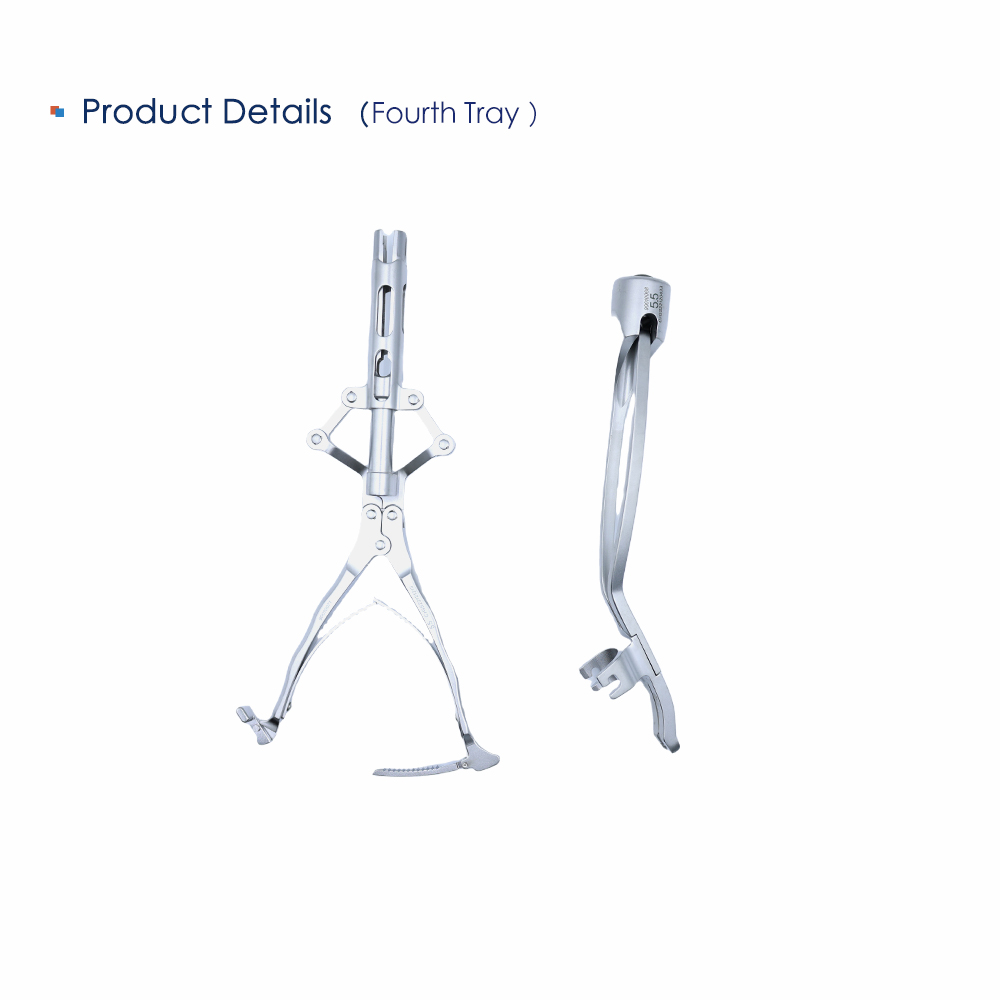
Rod work finishes in tray 4. A 25 mm trial rod and a 500 mm trial rod set the length; the fork rod holder and the cylindrical inserter put the rod into the screw heads; the compression forceps with green pads close the gap between two heads before the set screws go in.
Locking is done with the 12.5 Nm torque handle and the final lock driver SW6.35, with the counter sleeve 5.5 holding the head steady. Left and right in-situ benders are mirrored, not interchangeable.

Instrument Schedule: 51 Items, Codes and Quantities
The list below follows the system schedule line for line. Codes are the ordering reference; quantities are per set. Instrument names are normalized to standard workshop English: local labeling can differ by market.
| No. | Instrument | Specification | Qty | Code |
|---|---|---|---|---|
| 01 | Open cone | - | 1 | 90010001 |
| 02 | Circuit breaker | Straight, Ø3.2 mm | 1 | 90010003 |
| 03 | Circuit breaker | Straight, Ø3.5 mm | 1 | 90010004 |
| 04 | Circuit breaker | Straight, Ø2.5 mm | 1 | 90010002 |
| 05 | Bone probe, hard | - | 1 | 90010201 |
| 06 | Double-ended probe | 300 mm | 1 | 90010005 |
| 07 | Thread tap | Ø4.5 mm | 1 | 90010006 |
| 08 | Thread tap | Ø5.5 mm | 1 | 90010007 |
| 09 | Thread tap | Ø6.5 mm | 1 | 90010008 |
| 10 | Thread tap | Ø7.5 mm | 1 | 90010009 |
| 11 | Quick-load handle | Vertical ratchet | 2 | 90010105 |
| 12 | Nail driver | Universal, M9 | 1 | 90010060 |
| 13 | Nail driver | Single spindle, M9 | 1 | 90010061 |
| 14 | Reduction driver | Gimbal, M9 | 1 | 90010101 |
| 15 | Reduction driver | Monoaxial, M9 | 1 | 90010102 |
| 16 | Quick-change handle | T-handle | 1 | 90010062 |
| 17 | Torx plug driver | - | 1 | 90010063 |
| 18 | Torx plug driver | Extended | 1 | 90010103 |
| 19 | Trial rod | 25 mm | 1 | 90010223 |
| 20 | Rod bending pliers | - | 1 | 90010213 |
| 21 | Rod-holding forceps | 5.5 | 1 | 90010069 |
| 22 | Reduction forceps | Rocking, 5.5 | 1 | 90010072 |
| 23 | Reduction forceps | Long tail, 5.5 | 1 | 90010073 |
| 24 | Counter-torque sleeve | 5.5 | 1 | 90010108 |
| 25 | Final lock driver | SW6.35 | 1 | 90010075 |
| 26 | Torx starter | Domino | 1 | 90010076 |
| 27 | Curved spreader forceps | - | 1 | 90010036 |
| 28 | Curved compression forceps | - | 1 | 90010037 |
| 29 | Spinner wrench | SW4.0 | 1 | 90010217 |
| 30 | Pedicle screw tail cutter | Long arm | 1 | 90010107 |
| 31 | Screwdriver | 5.5 | 2 | 90010086 |
| 32 | Torque handle | 12.5 Nm | 1 | 90010090 |
| 33 | Screwdriver | Lengthened | 1 | 90010104 |
| 34 | Horizontal driver connector | SW3.5 | 1 | 90010025 |
| 35 | Diameter ruler | - | 1 | 90010093 |
| 36 | Transverse measuring stick | - | 1 | 90010094 |
| 37 | Pedicle locator | - | 1 | 90010095 |
| 38 | Guide pin | Columnar | 4 | 90010096 |
| 39 | Guide pin | Spherical | 4 | 90010097 |
| 40 | Transverse connector forceps | - | 1 | 90010041 |
| 41 | Rod press | 5.5 | 1 | 90010070 |
| 42 | Rod-holding forceps | Strong, 5.5 | 2 | 90010079 |
| 43 | In-situ rod bender, left | Sagittal plane, 5.5 | 1 | 90010081 |
| 44 | In-situ rod bender, right | Sagittal plane, 5.5 | 1 | 90010082 |
| 45 | Trial rod | 500 mm | 1 | 90010067 |
| 46 | Reduction forceps | Frog, 5.5 | 1 | 90010071 |
| 47 | Reduction sleeve | B 80 | 1 | 90010084 |
| 48 | Side-loading rod inserter | 5.5 | 1 | 90010087 |
| 49 | Side-loading rod handle | 5.5 | 1 | 90010088 |
| 50 | Step rod press | T-handle, SW14 | 1 | 90010089 |
| 51 | Instrument container | 4-tray, perforated | 1 | 90010098B |
| - | 50 instruments + 1 container | 51 coded lines | 60 | 90010098B |
Want the schedule as an editable file?
We can send this table as XLSX with your own item numbers in place of ours.
Which Instrument Goes With Which Step
Six steps, in the order the trays are opened. Individual codes are listed in the schedule above.
Localize the pedicle
Pedicle locator, guide pins columnar and spherical, horizontal connector SW3.5.
Open the tract
Open cone first, then the circuit breakers at Ø2.5, Ø3.2 and Ø3.5 mm.
Tap to screw diameter
Thread taps Ø4.5, Ø5.5, Ø6.5 and Ø7.5, driven by the vertical ratchet handle.
Insert the screw
Universal M9 driver or single-spindle M9 driver; the two reduction drivers for long-tab screws.
Measure, bend, seat the rod
25 mm and 500 mm trial rods, rod benders, the left and right in-situ benders, and the rod press.
Compress and lock
Compression forceps, counter sleeve 5.5, torque handle at 12.5 Nm, final lock driver.
Evaluating the set for a hospital tender?
We can ship a demo tray with the same layout for a hands-on review before order.
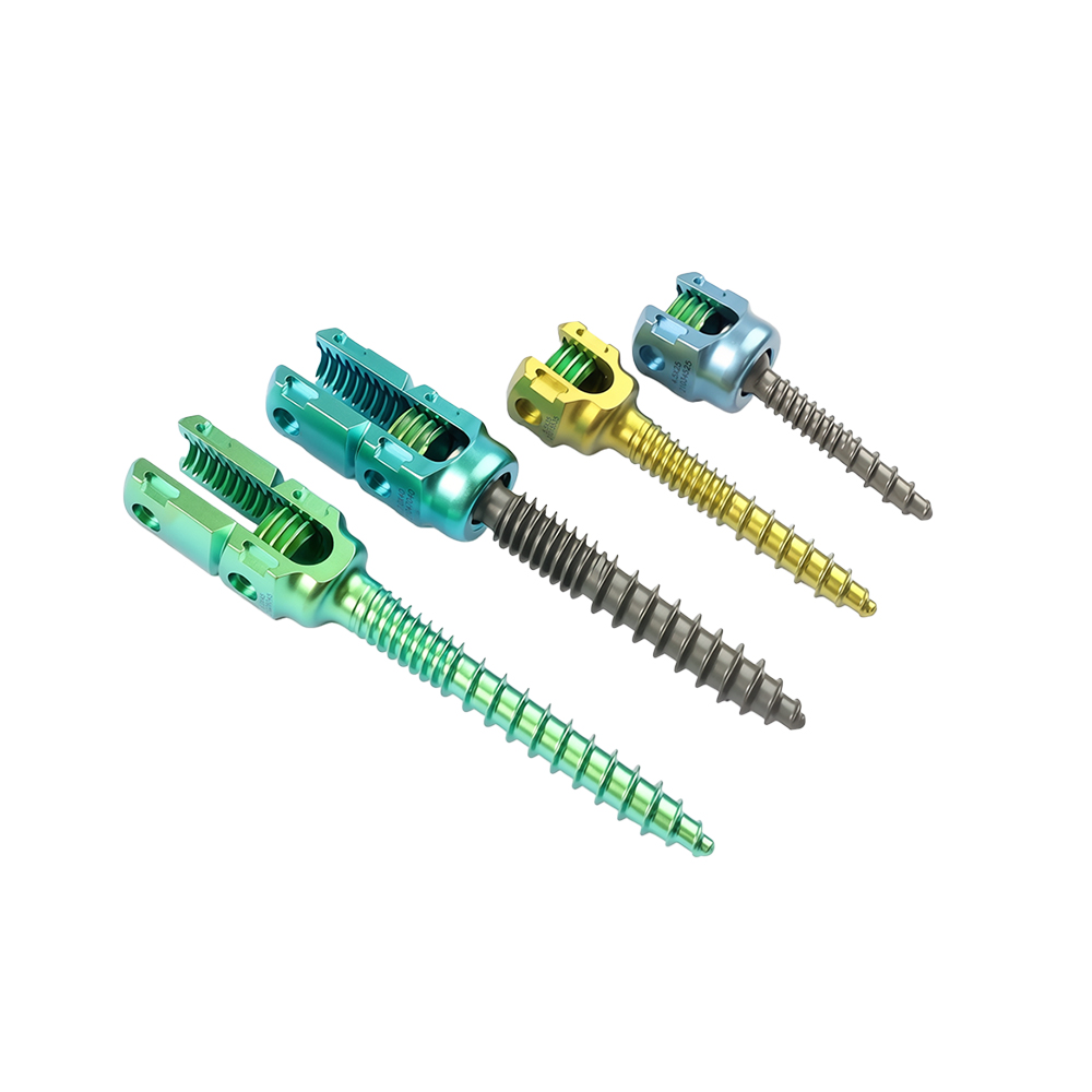
Four Screw Families on the Same Ø5.5 mm Rod
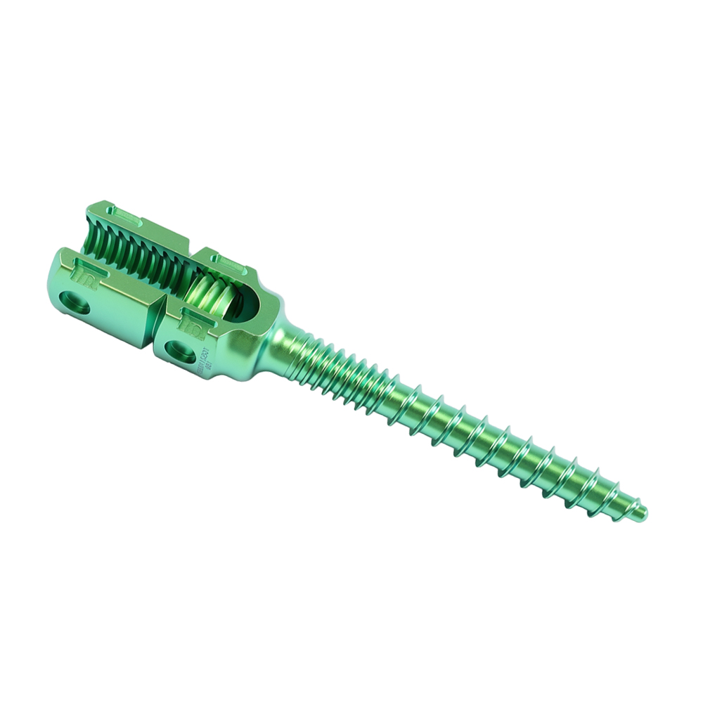
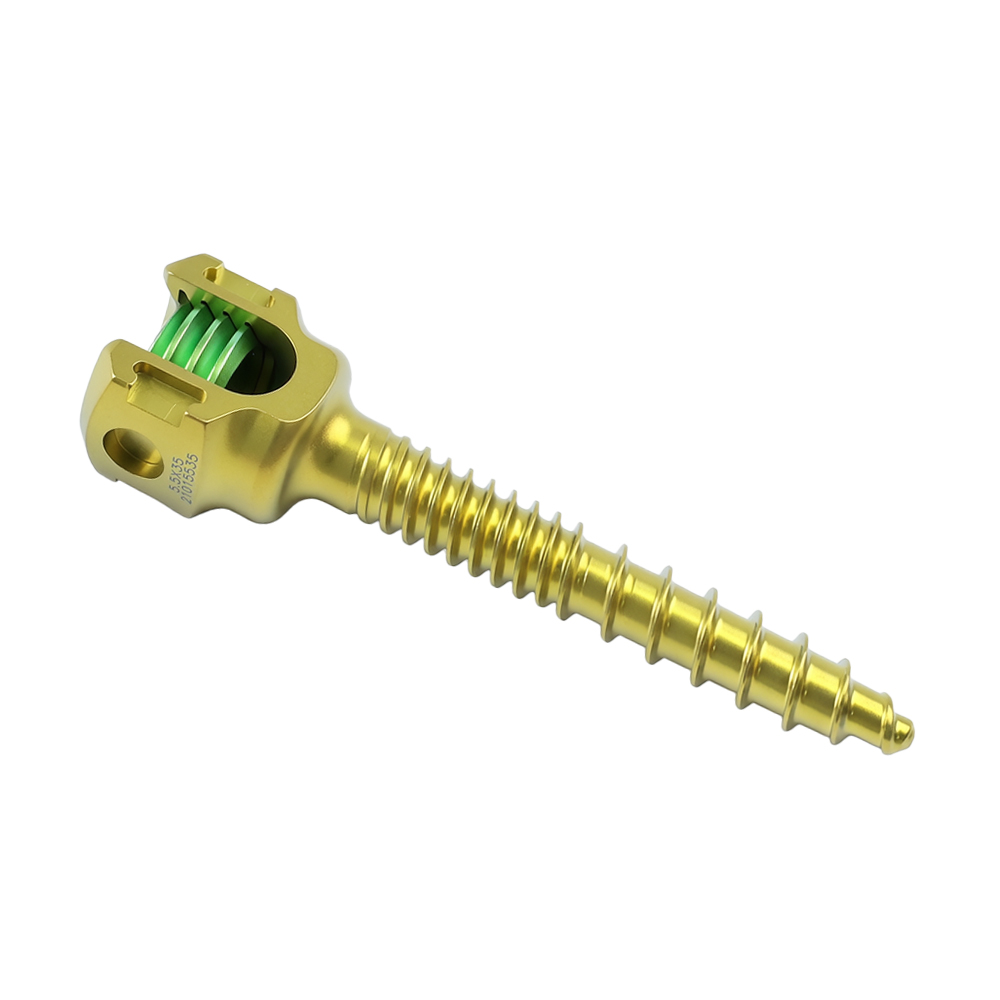
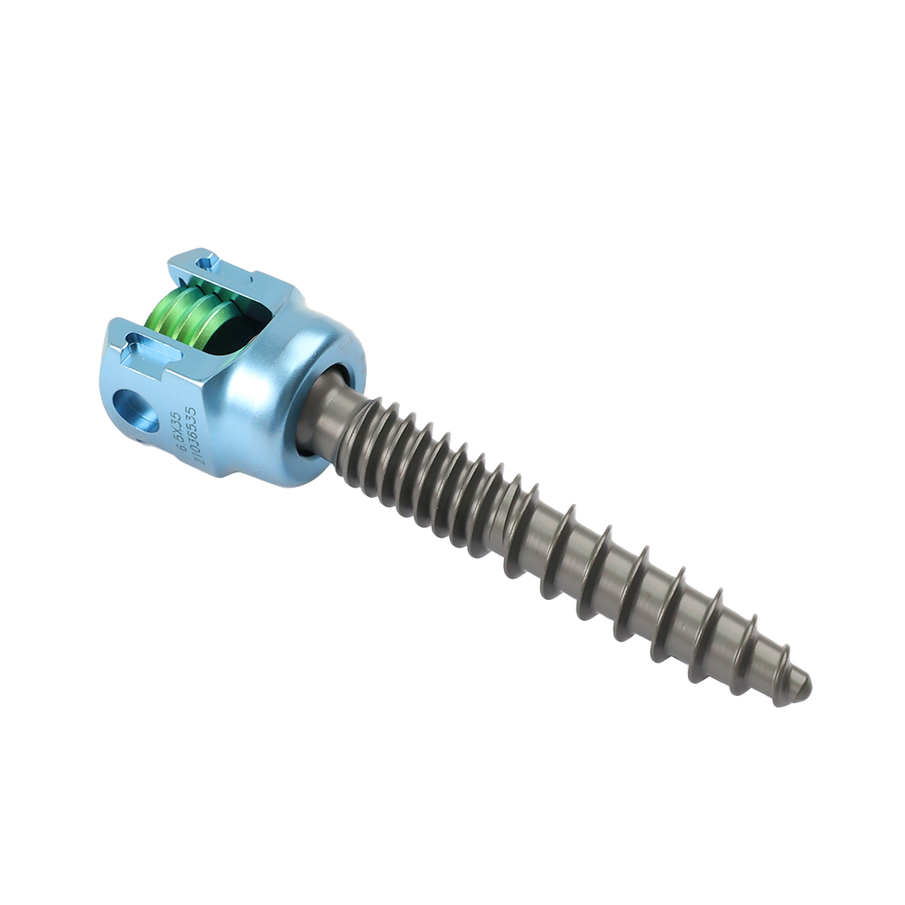
The instrument set is built for the 5.5 pedicle screw implant range, not for a single screw type. Monoaxial, polyaxial and the two reduction families share the same rod diameter, the same M9 driver interface and the same 12.5 Nm locking torque.
| Configuration | Sizes | Head |
|---|---|---|
| Monoaxial21014 | Ø4.0-7.5 mm, 25-55 mm | Fixed angle |
| Reduction monoaxial21024 | Ø4.0-7.5 mm, 25-55 mm | Extended reduction tabs |
| Polyaxial21034 | Ø4.0-7.5 mm, 25-55 mm | Multi-axial |
| Reduction polyaxial21044 | Ø4.0-7.5 mm, 25-55 mm | Multi-axial with reduction tabs |
Frequently Asked Questions
What is included in the 5.5 pedicle screw instrument set?
The set contains 51 coded line items: 50 instruments and one four-tray perforated container, 59 instrument pieces in total. Implants are not included.
Does the instrument set include screws and rods?
No. Screws, rods, set screws and cross connectors are ordered separately from the 5.5 Pedicle Screw System, code 21014, and its related families.
Which screw sizes does the kit prepare?
The four thread taps cover Ø4.5, Ø5.5, Ø6.5 and Ø7.5 mm, for implants from Ø4.0 to Ø7.5 mm and 25 to 55 mm in length.
Can the trays be steam sterilized?
The container lid and side walls are perforated, and all four trays are perforated. Reprocessing must follow the validated instructions for use supplied with the set and your hospital sterilization policy.
Is the tray layout customizable for OEM orders?
Yes. Trays are assembled to the approved packing list, and laser marking, anodized colors and packaging can be customized. Standard lead time is 7-14 days, 15-30 days for OEM orders.
What documentation is supplied with the set?
Material certificates, the instructions for use and certificate copies are supplied with the quotation. ISO, CE, FDA, FSC and MDSAP certification is listed for the 5.5 pedicle screw system.
Is the set compatible with polyaxial and reduction screws?
Yes. The same drivers, persuader and torque handle serve the monoaxial, polyaxial, reduction monoaxial and reduction polyaxial families on a Ø5.5 mm rod.
Ordering, OEM and Documentation
A standard set is built to the schedule above. Anything that differs: tray layout, marking, color, packaging: is handled as an OEM line with its own packing list and approval drawing.
| Item | Detail |
|---|---|
| Set reference | Four-tray perforated container, assembled to the 51-line instrument schedule |
| Implants | Separate order: 5.5 Pedicle Screw System, four configurations |
| Minimum order | 1 set |
| Lead time | 7-14 days standard, 15-30 days for OEM |
| OEM / ODM | Laser marking, custom anodized colors, custom packaging |
| Certification | ISO, CE, FDA, FSC and MDSAP, as listed for the 5.5 pedicle screw system |
| Instrument material | Stainless steel: grade stated on the packing list |
| Implant material | Ti-6Al-4V titanium alloy |
| Sterilization | Follow the instructions for use supplied with the set |
Send the case mix, get a set list back
Tell us the levels you usually fix and the screw families you stock. We will mark up this schedule against it and quote the difference.
Page last reviewed: November 2026.
Product information, not medical advice. Instrument names are normalized from the system schedule; codes and quantities follow that schedule. Confirm the packing list and the instructions for use before clinical use.


